BPD series PV pumping inverter Commissioning guide
64
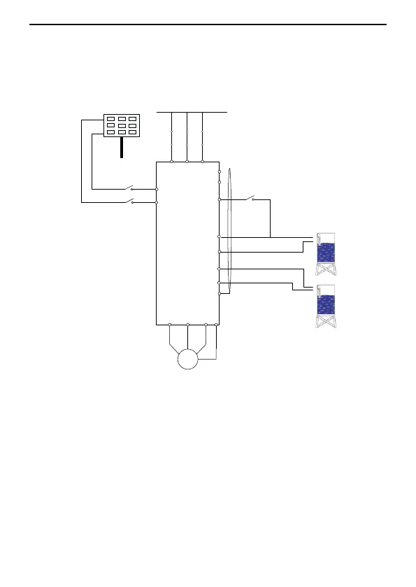
6.2 Commissioning on grid power supply
1. Perform the wiring according to the diagram and check whether the wiring is
performed properly.
Switch off Q2 and then switch on Q1, as shown in Figure 6.2.
Q1
The grid
S4
PV+
PV pumping inverter
M
U V W
L N PE
CO
M
S2
S3
COM
PE
485-
485+
PV-
Q2
PV solar panels
Run/Stop
Reservoir
PE
Full water signal
No-water signal
Figure 6.2 Wiring for grid power supply
2. Set the motor parameters
(1) Set P00.18=1 to restore the factory settings.
(2) Set the motor type through P02.00: 0 indicates 3PH motor and 1 indicates
1PH motor. You need to set P04.34 to 0x01 when the capacitor-removed 1PH
motor is drived in the 2PH control mode.
(3) Set the name plate of the motor, including P02.01, P02.02, P02.03, P02.04
and P02.05 (the maximum setting of P02.04 is 200V for the 1PH motor whose
capacitor is removed).
3. Set P15.29=1.
4. Detect water yield for water pumps
Click "Run" key, observe the running frequency and water yield. If the running
 Loading...