Goodrive270 series VFD for fan and pump Basic operation guidelines
-118-
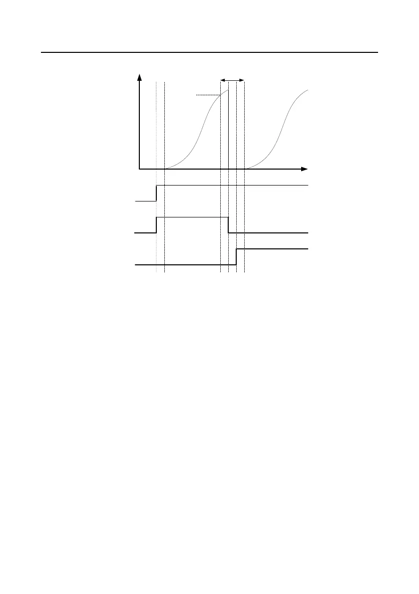
5.5.18.3 Motor adding
Output
frequency
t
1 2
3 4 5 6
Run status
RO1
RO2
Motor
connected
to RO1
Motor
connected to
RO1/2
ǏP94.36ǐ
ǏP94.20ǐ
ǏP94.21ǐ
ǏP94.37ǐ
ǏP94.36ǐ
Motor adding
Figure 5±8 Motor adding timing diagram
After the VFD is started, RO1 is closed, and the VFD temporarily does not make an output.
The VFD makes a modulated output after P94.36 (Contactor closing delay) elapsed.
During VFD running, if the output frequency is equal to or higher than P94.20 (Running frequency for
motor adding), PID1 feedback is less than the difference between PID1 reference and P94.19
(Pressure tolerance for motor adding), and this condition lasts a period of time longer than P94.21
(Motor adding delay), the motor adding function is triggered.
Motors are added, and then the VFD coasts to stop and disconnects the contactor with a contactor
opening delay (P94.37) to ensure completed disconnection.
The VFD closes the relay with a contactor closing delay (P94.36) to ensure completed closing.
Variable-frequency pumps are updated. Power-frequency pumps are updated with the similar logic.
For fixed variable-frequency pump wiring, the contactor is not disconnected during the motor adding
process.
 Loading...