Goodrive270 series VFD for fan and pump Basic operation guidelines
-80-
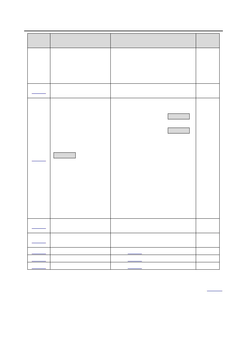
Function
Name Description Default
LED thousands place: Indicates whether to
enable the integral function through the ġ
/Ģ key and digital potentiometer.
0: Disable the integral function
1: Enable the integral function
P08.43
Keypad digital potentiometer
0.01±10.00s 0.10s
P08.44
UP/DOWN terminal control
setting
0x000±0x221
Ones place: Frequency setting selection
0: The setting made through UP/DOWN is
valid.
1: The setting made through UP/DOWN is
invalid.
Tens place: Frequency control selection
0: Valid only when P00.06=0 or P00.07=0
1: Valid for all frequency setting methods
2: Invalid for multi-step speed running
when multi-step speed running has the
priority
Hundreds place: Action selection for stop
0: Setting is valid.
1: Valid during running, cleared after stop
2: Valid during running, cleared after a stop
command is received
0x000
P08.45
Frequency increment change
rate of the UP terminal
0.01±50.00 Hz/s 0.50 Hz/s
P08.46
Frequency reduce rate of the
0.01±50.00 Hz/s 0.50 Hz/s
0.00Hz±P00.03(Max. output frequency)
0.00Hz±P00.03(Max. output frequency)
5.5.9 Analog input
The VFD carries two analog input terminals AI1 and AI2 and one high-speed pulse input terminal. AI1
supports 0(2)±10V/0(4)±20mA. Whether AI1 uses voltage input or current input can be set by P05.50,
and if the input type is current, the AI-I short cap on the control board needs to be shorted. AI2
supports -10±10V. Each input can be filtered separately, and the corresponding reference curve can
be set by adjusting the reference corresponds to the max. value and min. value.
 Loading...