Goodrive270 series VFD for fan and pump Function parameter list
-213-
Name Description Default
P19.09
AI3 of I/O card
±10.00V 0.00V ƽ
P19.10±
Reserved
P23 group²Vector control of motor 2
Name Description Default
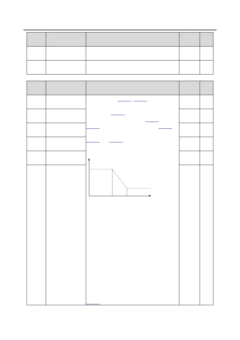
P23.00
Speed-loop
P23.00±P23.05 are applicable
only to vector control mode.
When switching
P23.02) is not reached, the
-loop PI parameters are: P23.00 and
. When switching frequency 2 (P23.05) is
, the speed-loop PI parameters are:
and P23.04. PI parameters are obtained
according to the linear change of two groups of
parameters. See the following figure:
PI parameters
Output frequency f
(P23.00,P23.01)
(P23.03,P23.04)
P23.02 P23.05
The speed loop dynamic response
characteristics o
f vector control can be adjusted
by setting the proportional coefficient and integral
time of speed regulator. Increasing proportional
gain or reducing integral time can accelerate
dynamic response of speed loop; however, if the
proportional gain is too la
rge or integral time is
too small, system oscillation and overshoot may
occur; if proportional gain is too small, stable
oscillation or speed offset may occur.
PI parameters have a close relationship with the
inertia of the system. Adjust PI parameters
dep
ending on different loads to meet various
P23.00 setting range: 0.0±200.0
20.0 ƻ
P23.01
Speed-
0.200s ƻ
P23.02
Low-
point frequency
for switching
5.00Hz ƻ
P23.03
Speed-loop
20.0 ƻ
P23.04
Speed-
0.200s ƻ
P23.05
-
for switching
10.00Hz ƻ
 Loading...