Goodrive270 series VFD for fan and pump Expansion card
-294-
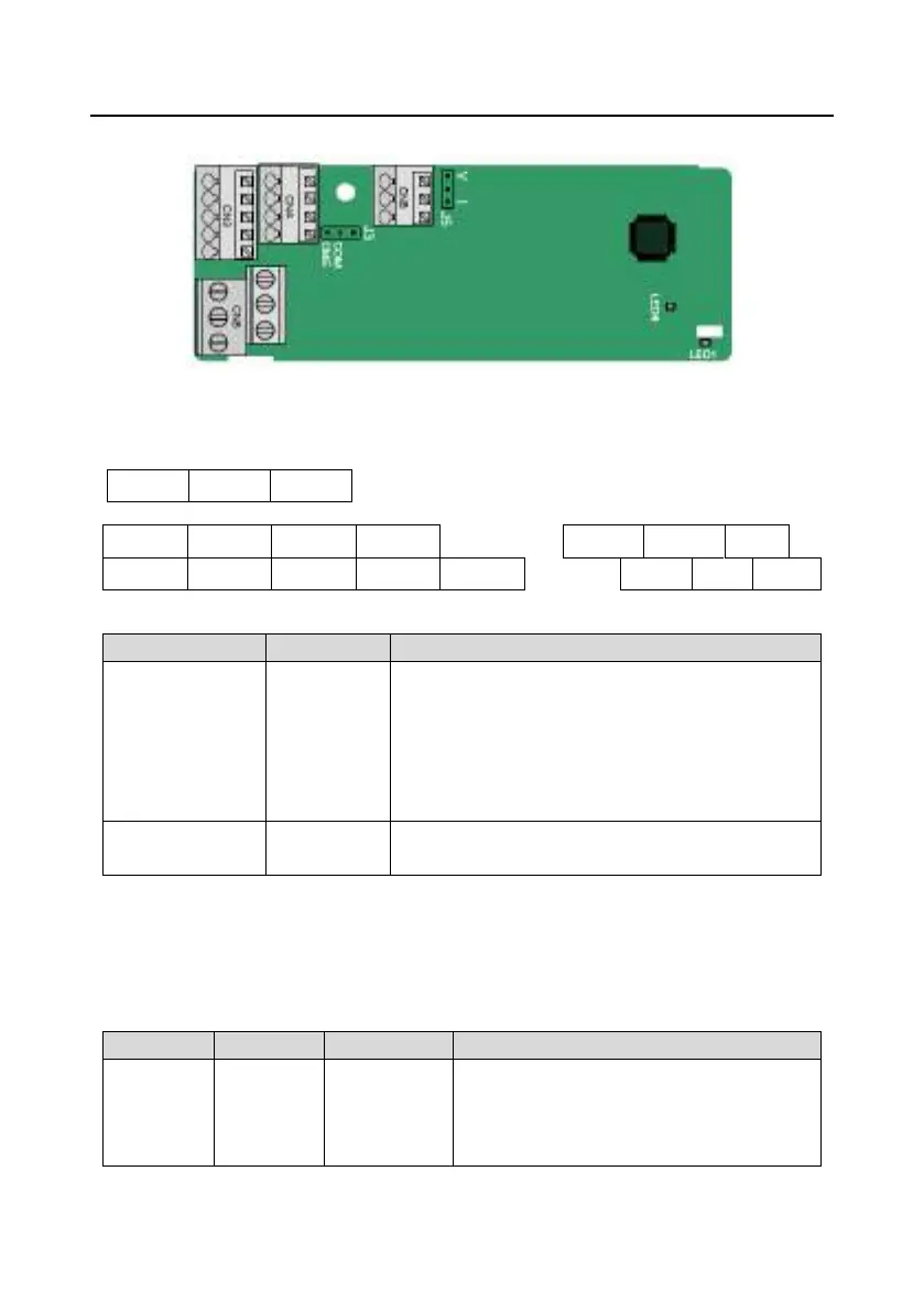
A.4 IO expansion card (EC-IO501-00)
The terminals are arranged as follows:
CME and COM are shorted through J3 before delivery, and J5 is the jumper for selecting the output
type (voltage or current) of AO2.
AI3 AO2 GND
COM CME Y2 S5
RO3A RO3B RO3C
PW +24V S6 S7 S8
RO4A RO4C
Indicator definition:
LED1
Status
indicator
This indicator is on when the expansion card is
establishing a connection with the control board;
it blinks periodically after the expansion card is properly
connected to the control board (the period is 1s, on for
0.5s, and off for the other 0.5s); and it is off when the
expansion card is disconnected from the control board.
LED4
Power
This indicator is on after the IO expansion card is
powered on by the control board.
EC-IO501-00 can be used in scenarios where the I/O interfaces of VFD cannot meet the application
requirements. It can provide 4 digital inputs, 1 digital output, 1 analog input, 1 analog output, and two
relay outputs. It is user-friendly, providing relay outputs through European-type screw terminals and
other inputs and outputs through spring terminals.
EC-IO501-00 terminal functions:
Power
supply
PW
External
power
Used to provide input digital working power
from the external to the internal.
Voltage range: 12±24V
PW and +24V have been short connected
 Loading...