Goodrive270 series VFD for fan and pump Expansion card
-295-
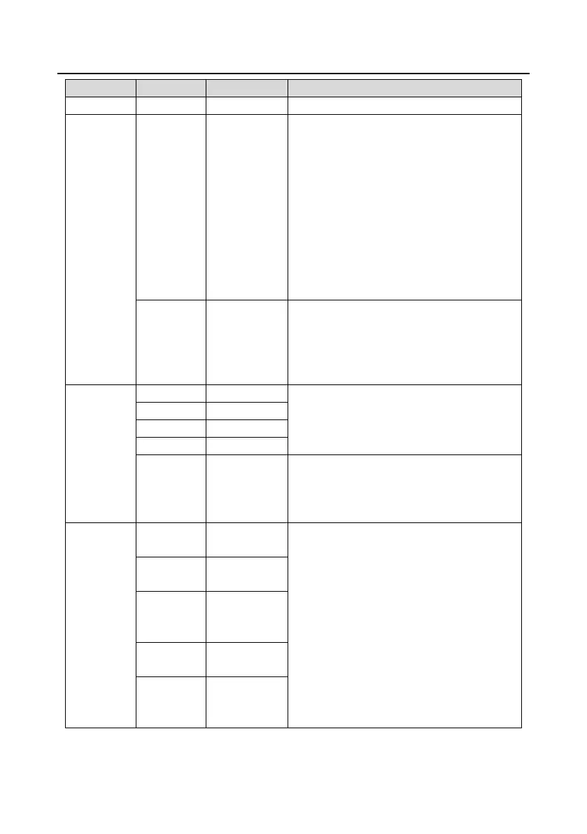
Analog
input/output
AI3²GND Analog input 1
1. Input range: For AI3, 0(2)±10V or 0(4)±
20mA
2. ,QSXWLPSHGDQFHNȍIRUYROWDJHLQSXW
ȍIRUFXUUHQWLQSXW
3. Whether voltage or current is used for
input is set through the corresponding
function code.
4. Resolution: 5mV when 10V corresponds to
50Hz
5. Deviation: ±0.5%; input of 5V or 10mA or
higher at the temperature of 25°C
AO2²GND
Analog output
1
1. Output range: 0(2)±10V or 0(4)±20mA
2. Whether voltage or current is used for
output is set through the jumper J5
3. Deviation: ±0.5%; output of 5V or 10mA or
higher at the temperature of 25°C
Digital
input/output
1. ,QWHUQDOLPSHGDQFHNȍ
2. 12±24V voltage input is acceptable
3. Bi-direction input terminal
4. Max. input frequency: 1kHz
Y2²CME Digital output
1. Switch capacity: 200mA/30V
2. Output frequency range: 0±1kHz
3. The terminals CME and COM are shorted
through J3 before delivery.
Relay
output
RO3A
NO contact of
1. Contact capacity: 3A/AC250V, 1A/DC30V
2. Cannot be used as high frequency digital
output.
RO3B
NC contact of
RO3C
Common
contact of
RO4A
NO contact of
RO4C
Common
contact of
 Loading...