101
P10.02 multi-stage speed 0
P10.03 the running time of stage 0
P10.04 mul ti-stage speed 1
P10.05 the running time of stage 1
P10.06 mul ti-stage speed 2
P10.07 the running time of stage 2
P10.08 mul ti-stage speed 3
P10.09 the running time of stage 3
P10.10 mul ti-stage speed 4
P10.11 the running time of stage 4
P10.12 mul ti-stage speed 5
P10.13 the running time of stage 5
P10.14 mul ti-stage speed 6
P10.15 the running time of stage 6
P10.16 mul ti-stage speed 7
P10.17 the running time of stage 7
P10.18 mul ti-stage speed 8
P10.19 the running time of stage 8
P10.20 mul ti-stage speed 9
P10.21 the running time of stage 9
P10.22 mul ti-stage speed 10
P10.23 the running time of stage
10
P10.24 mul ti-stage speed 11
P10.25 the running time of stage
11
P10.26 mul ti-stage speed 12
P10.27 the running time of stage
12
P10.28 mul ti-stage speed 13
P10.29 the running time of stage
13
P10.30 mul ti-stage speed 14
P10.31 the running time of stage
14
P10.32 mul ti-stage speed 15
P10.33 the running time of stage 15
BIT0
BIT1
BIT2
BIT3
BIT4
BIT5
BIT6
BIT7
BIT8
BIT9
BIT10
BIT11
BIT12
BIT13
BIT14
BIT15
Terminal function 16
Multi-stage speed 1
Terminal function 17
Multi-stage speed 2
Terminal function 18
Multi-stage speed
terminal 3
Terminal function 19
Multi-stage speed
terminal 1
P10.34
The ACC/DEC time selection
of Stage 0~7 of PLC
P00.10 ACC time 1
P00.12 DEC time 1
P08.00 ACC time 2
P08.01 D EC time 2
P08.02 ACC time 3
P08.03 DEC time 3
P08.04 ACC time 4
P08.15 DEC time 4
00
01
10
11
BIT0
BIT1
BIT2
BIT3
BIT4
BIT5
BIT6
BIT7
BIT8
BIT9
BIT10
BIT11
BIT12
BIT13
BIT14
BIT15
P00.10 ACC time 1
P00.12 DEC time 1
P08.00 ACC time 2
P08.01 D EC time 2
P08.02 ACC time 3
P08.03 DEC time 3
P08.04 ACC time 4
P08.15 D EC time 4
00
01
10
11
The ACC/DEC time selection
of Stage 8~15 of PLC
Multi-stage speed
output
Runni ng command
Multi-stage
speed 0
Multi-stage
speed 1
Multi-stage
speed 15
ON
OFF
OFF ON
Terminal function 16
Multi-stage speed
terminal 1
Terminal function 17
Multi-stage speed
terminal 2
Terminal function 18
Multi-stage speed
terminal 3
Terminal function 19
Multi-stage speed
terminal 4
OFF ON OFF ON OFF ON
OFF ONOFF ON OFFON OFF ON
OFF ONOFF ONOFF ONOFF ON
Multi-stage
speed
8 9 10 11 12 13 14 15
ON ONON ON ON ONON ON
OFF ON
Terminal function 16
Multi-stage speed
terminal 1
Terminal function 17
Multi-stage speed
terminal 21
Terminal function 18
Multi-stage speed
terminal 3
Terminal function 19
Multi-stage speed
terminal 4
OFF ON OFF ON OFF ON
OFF ONOFF ON OFFON OFF ON
OFF ONOFF ONOFF ONOFF ON
OFF OFF OFF OFF OFF OFF OFF OFF
Multi-stage
speed
0 1 2 3 4 5 6 7
Frequency
retention
Valid
Invalid
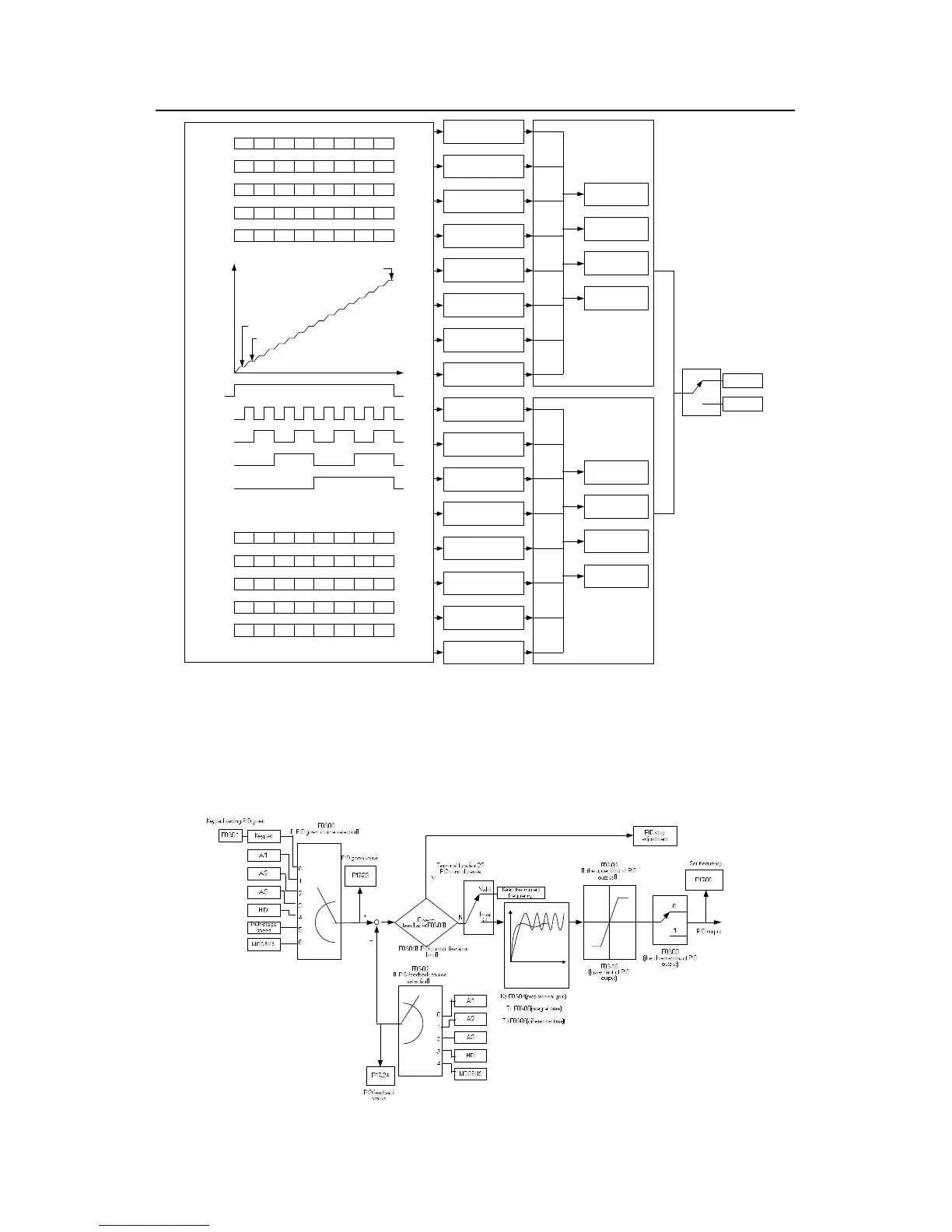
7.10 PID control
PID control is commonly used to control the procedure. Adjust the output frequency by
proportional, integral, differential operation with the dispersion of the target signals to
stabilize the value on the target. It is possible to apply to the flow, pressure and temperature
control. Figure of basic control is as below:
 Loading...


