resolution
Terminal switch input
resolution
≤ 2ms
Analog input
1 channels ( AI2) 0~10V/0~20mA and 1 channel
(AI3) -10~10V
Analog output 2 channels (AO1, AO2) 0~10V /0~20mA
Digital input
8 channels common input, the Max. frequency:
1kHz, internal impedance: 3.3kΩ;
1 channel high speed input, the Max. frequency:
50kHz
Digital output
1 channel high speed pulse output, the Max.
frequency: 50kHz;
1 channel Y terminal open collector pole output
Relay output
2 channels programmable relay output
RO1A NO, RO1B NC, RO1C common terminal
RO2A NO, RO2B NC, RO2C common terminal
Contactor capability: 3A/AC250V,1A/DC30V
Others
-10~50℃, derate above 40℃
Ingress protection IP20
Cooling Air-cooling
Braking unit
Built-in braking unit for inverters below 30kW
(including 30kW)
External braking unit for others
EMC filter
Built-in C3 filter: meet the degree requirement of
IEC61800-3 C3
External optional filter:meet the degree requirement
of IEC61800-3 C2
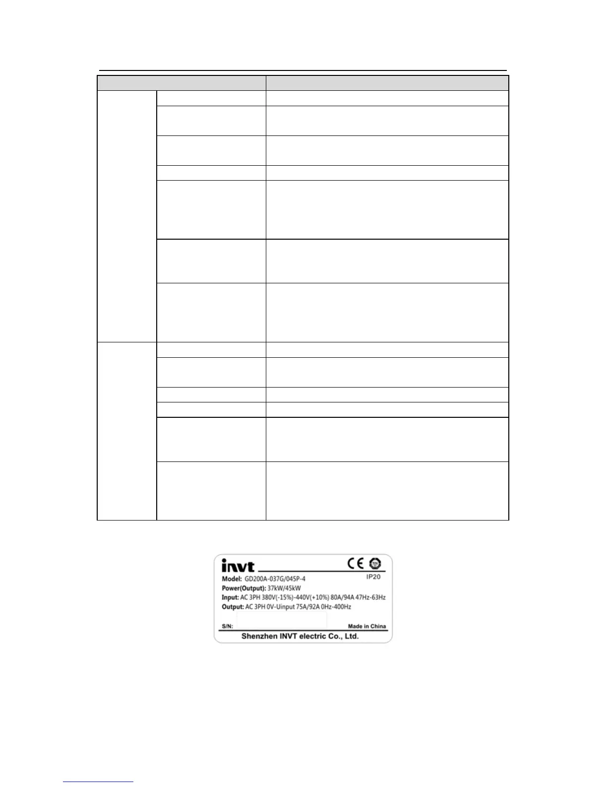
3.4 Name plate
Fig 3-3 Name plate
Note: This is the example of the name plate for the standard products, and CE\TUV\IP20 will
be marked according to the actual situations.