155
C.9 Other optional parts
No.
Optional
part
Instruction Picture
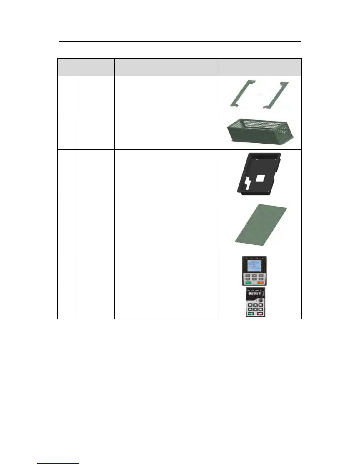
1
Flange
installation
bracket
Needed for the flange installation of
1.5~30kW inverters
Not needed for the flange installation
of 37~200kW inverters
2
Installation
base
Optimal for 220~315kW inverters
An input AC/DC reactor and output
AC reactor can be put in the base.
Use the screw or installation bracket
to fix the external keypad.
Optimal for 1.5~30kW inverters ands
standard for 37~500kW inverters
Protect the internal circuit in serious
environment. Derate when selecting
the cover. Please contact INVT for
detailed information.
5
LCD
Support several languages,
parameters copy, high-definition
display and the installation dimension
is compatible with the LED keypad.
0.75~15kW inverter optional.