Increase the power of the braking resistor properly in the frequent
braking situation (the frequency usage ratio is more than 10%).
C.8.2 Select the brake resistor cables
Use a shielded cable to the resistor cable.
C.8.3 Place the brake resistor
Install all resistors in a place where they will cool.
The materials near the brake resistor must be non-flammable. The
surface temperature of the resistor is high. Air flowing from the resistor
is of hundreds of degrees Celsius. Protect the resistor against contact.
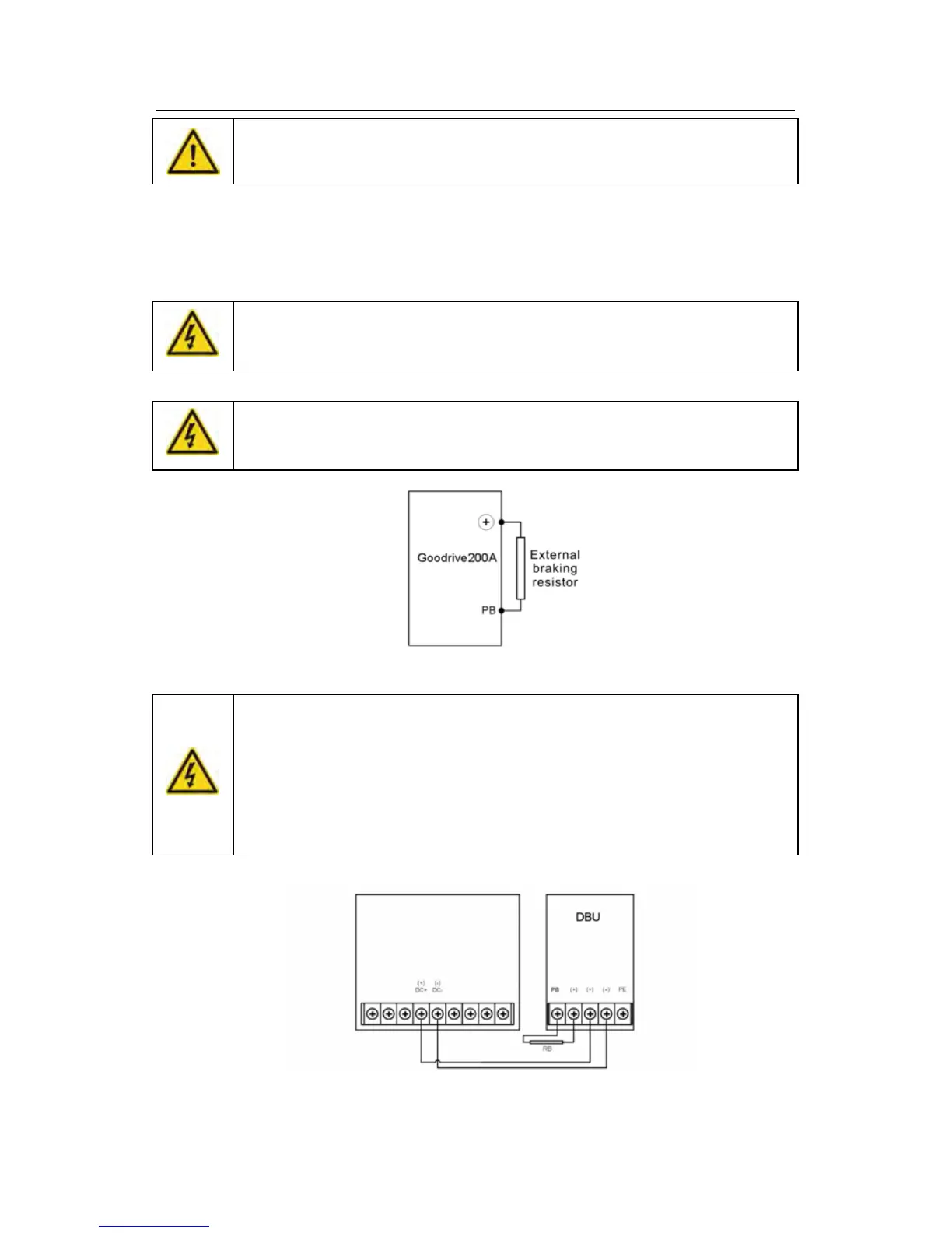
Installation of the braking resistor:
The inverters below30kW (including 30kW) only needs external braking
resistors.
PB and (+) are the wiring terminals of the braking resistors.
Installation of braking units:
The inverters above 37kW (including 370kW) only needs external
braking units.
(+), (-) are the wiring terminals of the braking units.
The wiring length between the (+),(-) terminals of the inverter and the
(+),(-) terminals of the braking units should be no more than 5m,and the
distributing length among BR1 and BR2 and the braking resistor
terminals should be no more than 10m.
Signal installation is as below: