119
9.3 Application of the inverter
The MODBUS protocol of the inverter is RTU mode and the physical layer is 2-wire RS485.
9.3.1 RS485
The interface of 2-wire RS485 works on semiduplex and its data signal applies differential
transmission which is called balance transmission, too. It uses twisted pairs, one of which is
defined as A (+) and the other is defined as B (-). Generally, if the positive electrical level
between sending drive A and B is among +2~+6V, it is logic“1”, if the electrical level is among
-2V~-6V; it is logic“0”.
485+ on the terminal board corresponds to A and 485- to B.
Communication baud rate means the binary bit number in one second. The unit is bit/s (bps).
The higher the baud rate is, the quicker the transmission speed is and the weaker the
anti-interference is. If the twisted pairs of 0.56mm(24AWG)is applied as the communication
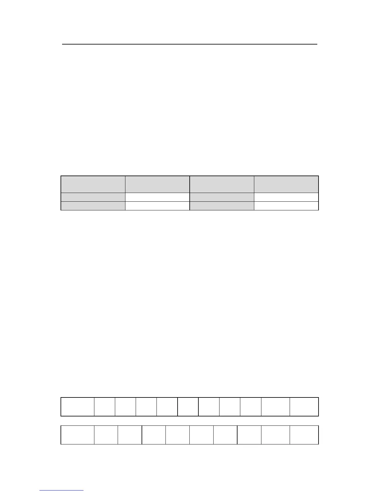
cables, the Max. Transmission distance is as below:
Baud rate
Max. transmission
distance
Baud rate
Max. transmission
distance
2400BPS 1800m 9600BPS 800m
4800BPS 1200m 19200BPS 600m
It is recommended to use shield cables and make the shield layer as the grounding wires
during RS485 remote communication.
In the cases with less devices and shorter distance, it is recommended to use 120Ω terminal
resistor as the performance will be weakened if the distance increase even though the
network can perform well without load resistor.
9.3.2 RTU mode
9.3.2.1 RTU communication frame format
If the controller is set to communicate by RTU mode in MODBUS network every 8bit byte in
the message includes two 4Bit hex characters. Compared with ACSII mode, this mode can
send more data at the same baud rate.
Code system
· 1 start bit
· 7 or 8 digital bit, the minimum valid bit can be sent firstly. Every 8 bit frame includes two
hex characters (0...9, A...F)
· 1 even/odd check bit . If there is no checkout, the even/odd check bit is inexistent.
· 1 end bit (with checkout), 2 Bit(no checkout)
Error detection field
· CRC
The data format is illustrated as below:
11-bit character frame (BIT1~BIT8 are the digital bits)
Start bit BIT1