120
In one character frame, the digital bit takes effect. The start bit, check bit and end bit is used
to send the digital bit right to the other device. The digital bit, even/odd checkout and end bit
should be set as the same in real application.
The MODBUS minimum idle time between frames should be no less than 3.5 bytes. The
network device is detecting, even during the interval time, the network bus. When the first
field (the address field) is received, the corresponding device decodes next transmitting
character. When the interval time is at least 3.5 byte, the message ends.
The whole message frame in RTU mode is a continuous transmitting flow. If there is an
interval time (more than 1.5 bytes) before the completion of the frame, the receiving device
will renew the uncompleted message and suppose the next byte as the address field of the
new message. As such, if the new message follows the previous one within the interval time
of 3.5 bytes, the receiving device will deal with it as the same with the previous message. If
these two phenomena all happen during the transmission, the CRC will generate a fault
message to respond to the sending devices.
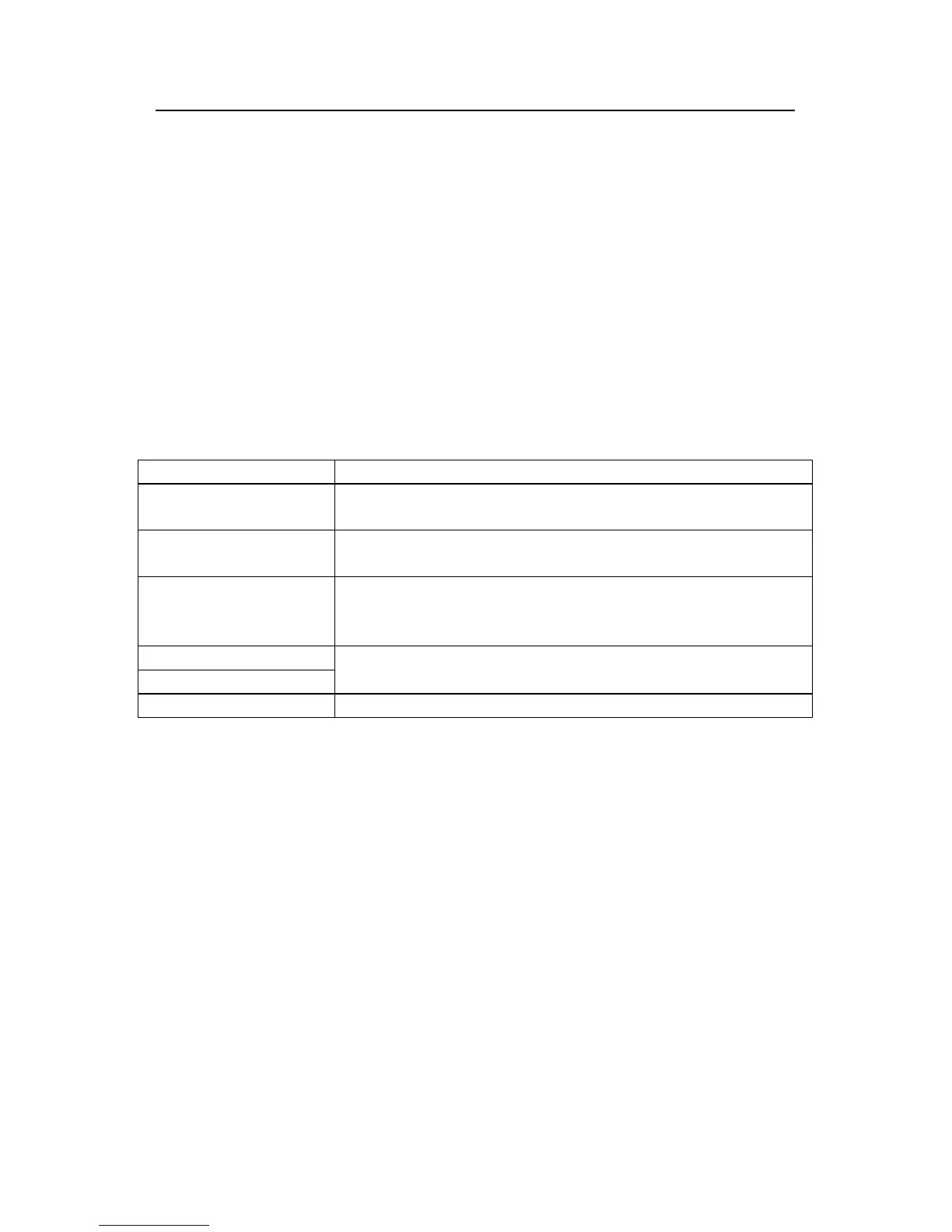
The standard structure of RTU frame:
START T1-T2-T3-T4(transmission time of 3.5 bytes)
ADDR
C
ommunication address: 0~247(decimal system)(0 is the broadcast
address)
CMD
03H:read slave parameters
06H:write slave parameters
DATA (N-1)
…
DATA (0)
T
he data of 2*N bytes are the main content of the communication as
well as the core of data exchanging
CRC CHK low bit
Detection value:CRC (16BIT)
CRC CHK high bit
END T1-T2-T3-T4(transmission time of 3.5 bytes)
9.3.2.2 RTU communication frame error checkout
Various factors (such as electromagnetic interference) may cause error in the data
transmission. For example, if the sending message is a logic “1”,A-B potential difference on
RS485 should be 6V, but in reality, it may be -6V because of electromagnetic interference,
and then the other devices take the sent message as logic“0”. If there is no error checkout,
the receiving devices will not find the message is wrong and they may give incorrect
response which cause serious result. So the checkout is essential to the message.
The theme of checkout is that: the sender calculate the sending data according to a fixed
formula, and then send the result with the message. When the receiver gets this message,
they will calculate anther result according to the same method and compare it with the
sending one. If two results are the same, the message is correct. If not, the message is
incorrect.
The error checkout of the frame can be divided into two parts: the bit checkout of the byte
and the whole data checkout of the frame (CRC check).
Bit checkout of the byte
The user can select different bit checkouts or non-checkout, which impacts the check bit