16
4.3 Standard wiring
4.3.1 Wiring diagram of main circuit
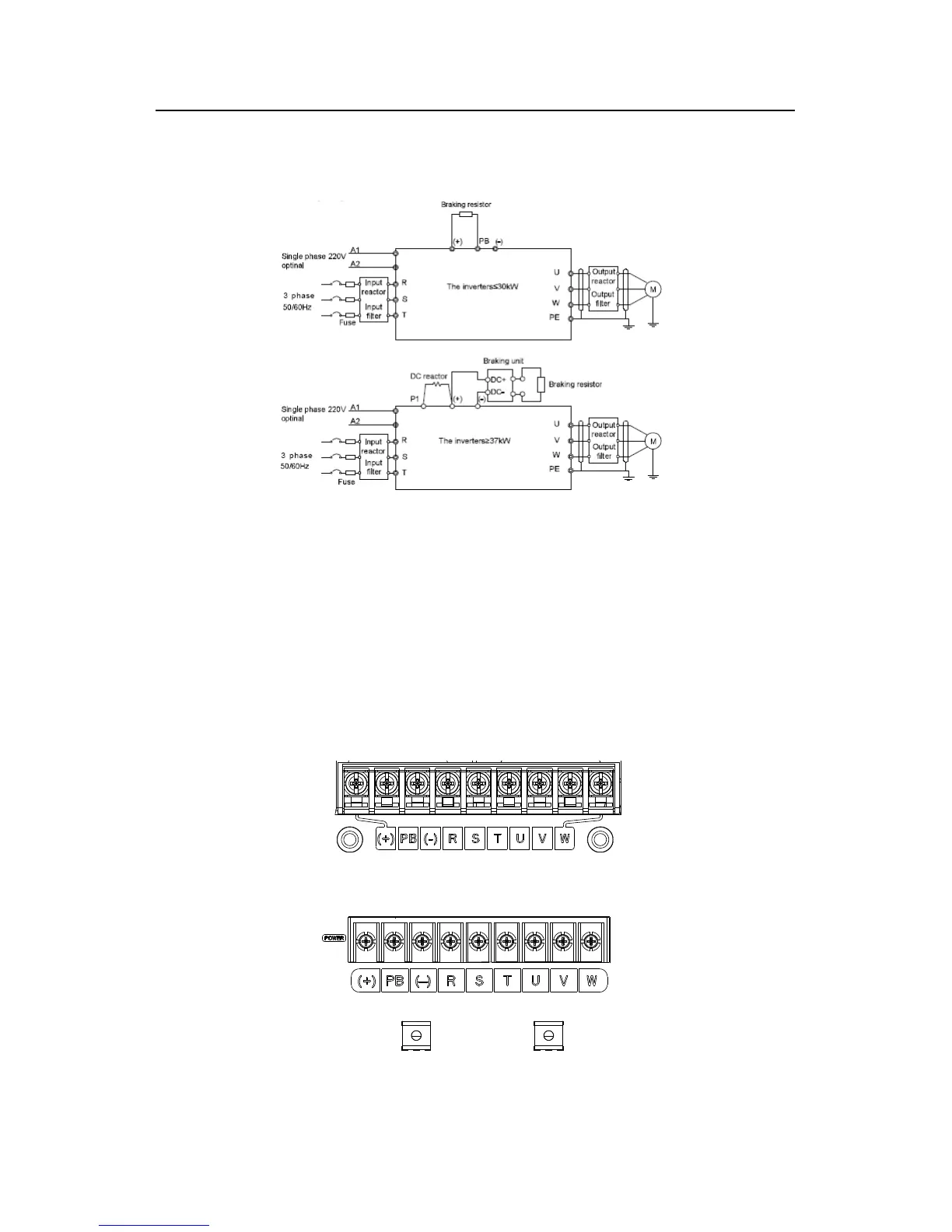
Fig 4-6 Wring diagram of main circuit
Note:
The fuse, DC reactor, braking unit, braking resistor, input reactor, input filter, output
reactor, output filter are optional parts. Please refer to Peripheral Optional Parts for
detailed information.
A1 and A2 are optional parts.
P1 and (+) are short circuited in factory, if need to connect with the DC rector, please
remove the contact tag between P1 and (+).
4.3.2 Terminals figure of main circuit
Fig 4-7 0.75~5.5 kW terminals of main circuit
Fig 4-8 7.5~15kW terminals of main circuit