152
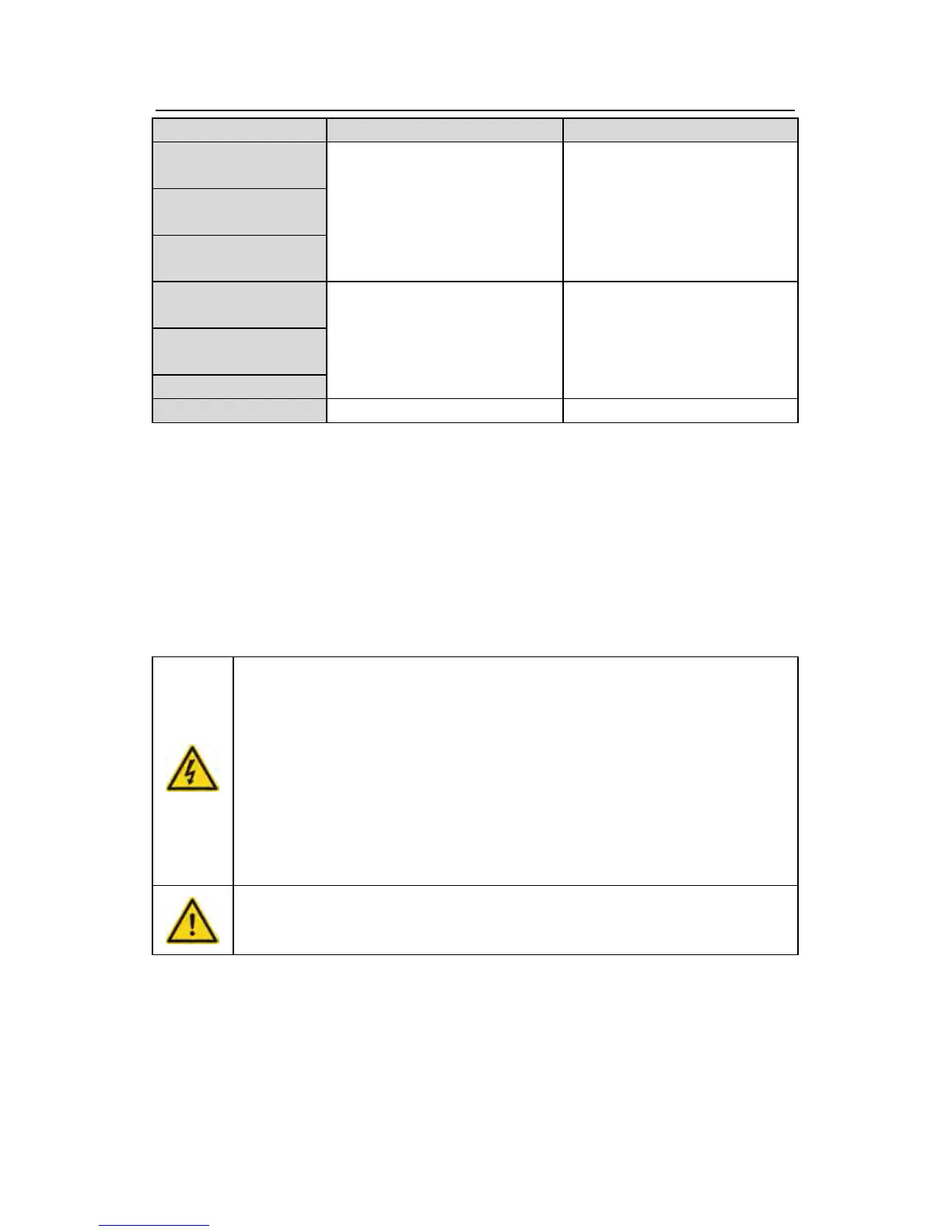
The inverter Input filter Output filter
GD200A
-220G/250P-4
FLT-P04600L-B FLT-L04600L-B
GD200A
-250G/280P-4
GD200A
-280G/315P-4
GD200A
-315G/350P-4
FLT-P04800L-B FLT-L04800L-B GD200A
-350G/400P-4
GD200A -400G-4
GD200A -500G-4 FLT-P041000L-B FLT-L041000L-B
Note: The input EMI meet the requirement of C2 after adding input filters.
C.8 Braking system
C.8.1 Select the braking components
It is appropriate to use braking resistor or braking unit when the motor brakes sharply or the
motor is driven by a high inertia load. The motor will become a generator if its actual rotating
speed is higher than the corresponding speed of the reference frequency. As a result, the
inertial energy of the motor and load return to the inverter to charge the capacitors in the
main DC circuit. When the voltage increases to the limit, damage may occur to the inverter. It
is necessary to apply braking unit/resistor to avoid this accident happens.
Only qualified electricians are allowed to design, install, commission
and operate on the inverter.
Follow the instructions in “warning” during working. Physical injury or
death or serious property may occur.
Only qualified electricians are allowed to wire. Damage to the inverter
or braking options and part may occur. Read carefully the instructions of
braking resistors or units before connecting them with the inverter.
Do not connect the braking resistor with other terminals except for PB
and (-). Do not connect the braking unit with other terminals except for (+)
and (-). Damage to the inverter or braking circuit or fire may occur.
Connect the braking resistor or braking unit with the inverter according
to the diagram. Incorrect wiring may cause damage to the inverter or
other devices.
Goodrive200A series inverters below 30kW (including 30kW) need internal braking units and
the inverters above 37kW need external braking unit. Please select the resistance and
power of the braking resistors according to actual utilization.
Note:
Select the resistor and power according to the provided data.
The braking torque may increase because of the raising of braking resistor. The below table