3.1 What this chapter contains
The chapter briefly describes the operation principle, product characteristics, layout, name
plate and type designation information.
3.2 Basic principles
Goodrive200A series inverters are wall, flange and mountable devices for controlling
asynchronous AC inductance motors.
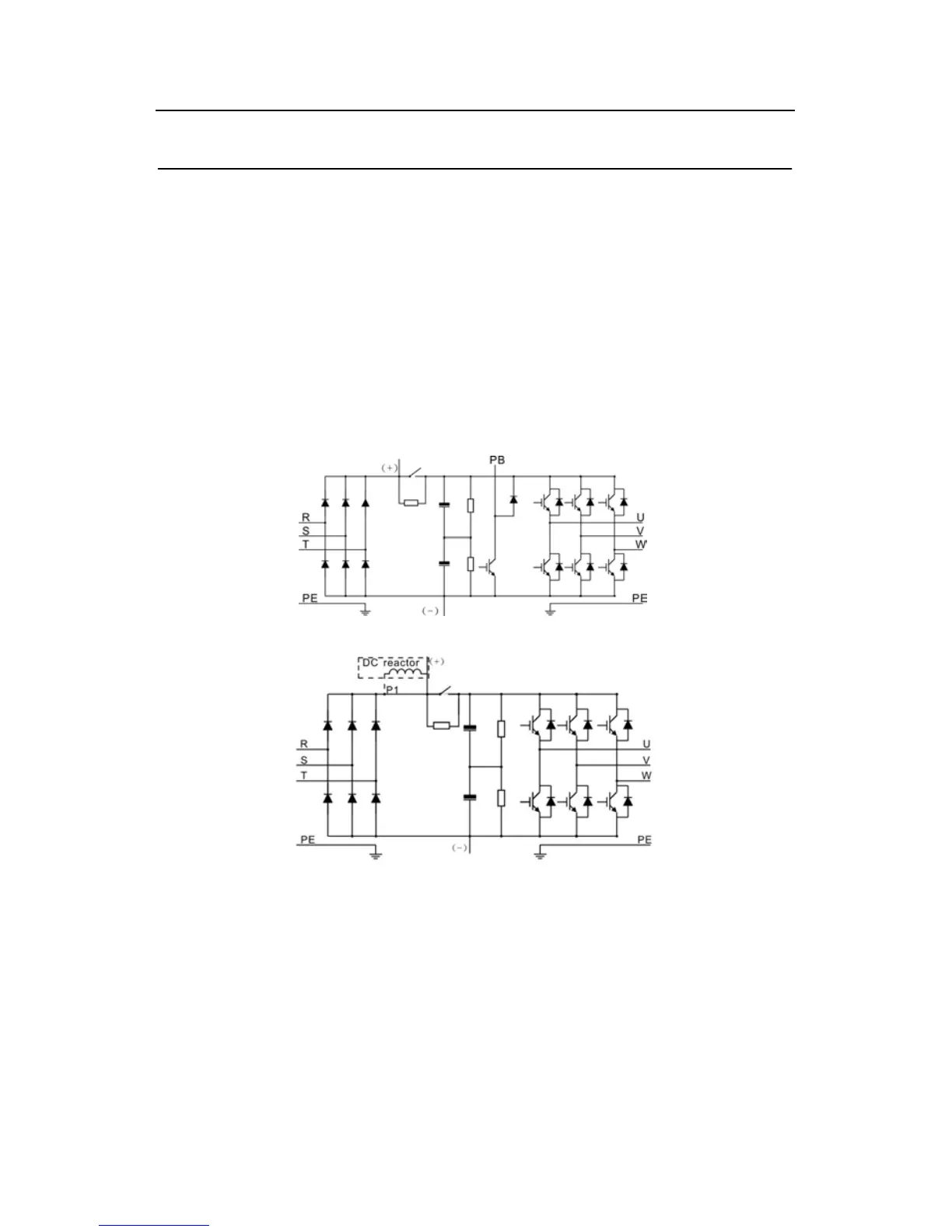
The diagram below shows the main circuit diagram of the inverter. The rectifier converts
three-phase AC voltage to DC voltage. The capacitor bank of the intermediate circuit
stabilizes the DC voltage. The converter transforms the DC voltage back to AC voltage for
the AC motor. The brake pipe connects the external braking resistor to the intermediate DC
circuit to consume the feedback energy when the voltage in the circuit exceeds its maximum
limit.
Diagram 3-1 The main circuit diagram (≤30kW)
Diagram 3-2 The main circuit diagram (≥37kW)
Note:
1. The inverter above 37kW (including 37kW) supports external DC reactor which is an
optional part. Before connecting, it is necessary to remove the copper row between P1 and
(+).
2. The inverters (≤30kW) have standard embedded braking units and the braking resistor is
optional.
3. The inverters (≥37kW) can be installed with optional braking units and the braking unit
and resistor are optional.