134
Function
instruction
Address
Data meaning instruction
R/W
characteristics
control
command
0002H:reverse running
0003H:forward jogging
0004H:reverse jogging
0005H:stop
0006H:coast to stop (emergency stop)
0007H:fault reset
0008H:jogging stop
The address of
communication
setting
2001H
Communication setting
frequency(0~Fmax(unit: 0.01Hz))
W/R
2002H
PID given, range(0~1000, 1000 corresponds
to100.0% )
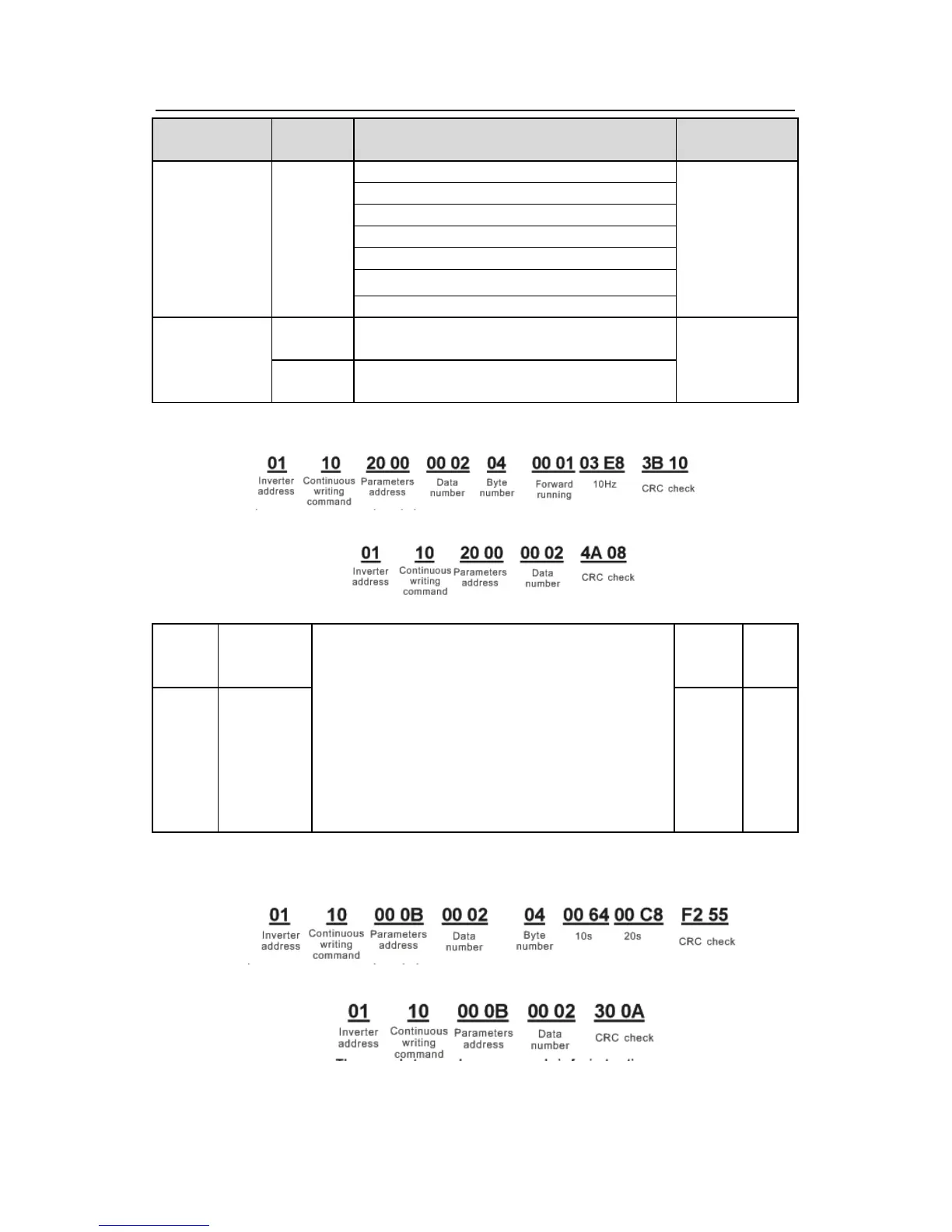
Set P00.01 to 2 and P00.06 to 8.
The command sent to the inverter:
If the response message is as below:
Example 2: set the ACC time of 01H inverter as 10s and the DEC time as 20s
P00.11
ACC time means the time needed if the inverter
speeds up from 0Hz to the Max. One (P00.03).
DEC time means the time needed if the inverter
speeds down from the Max. Output frequency to
0Hz (P00.03).
Goodrive300 series inverters define four groups of
ACC/DEC time which can be selected by P05. The
factory default ACC/DEC time of the inverter is the
first group.
Setting range of P00.11 and P00.12:0.0~3600.0s
Depend
on
model
○
The corresponding address of P00.11 is 000B, the ACC time of 10s corresponds to 0064H,
and the DEC time of 20s corresponds to 00C8H.
The command sent to the inverter:
If the response message is as below:
Note: The space between above commands is for instruction and there is no space between
the commands during actual applications.