Goodrive200A inverters Keypad operation procedure
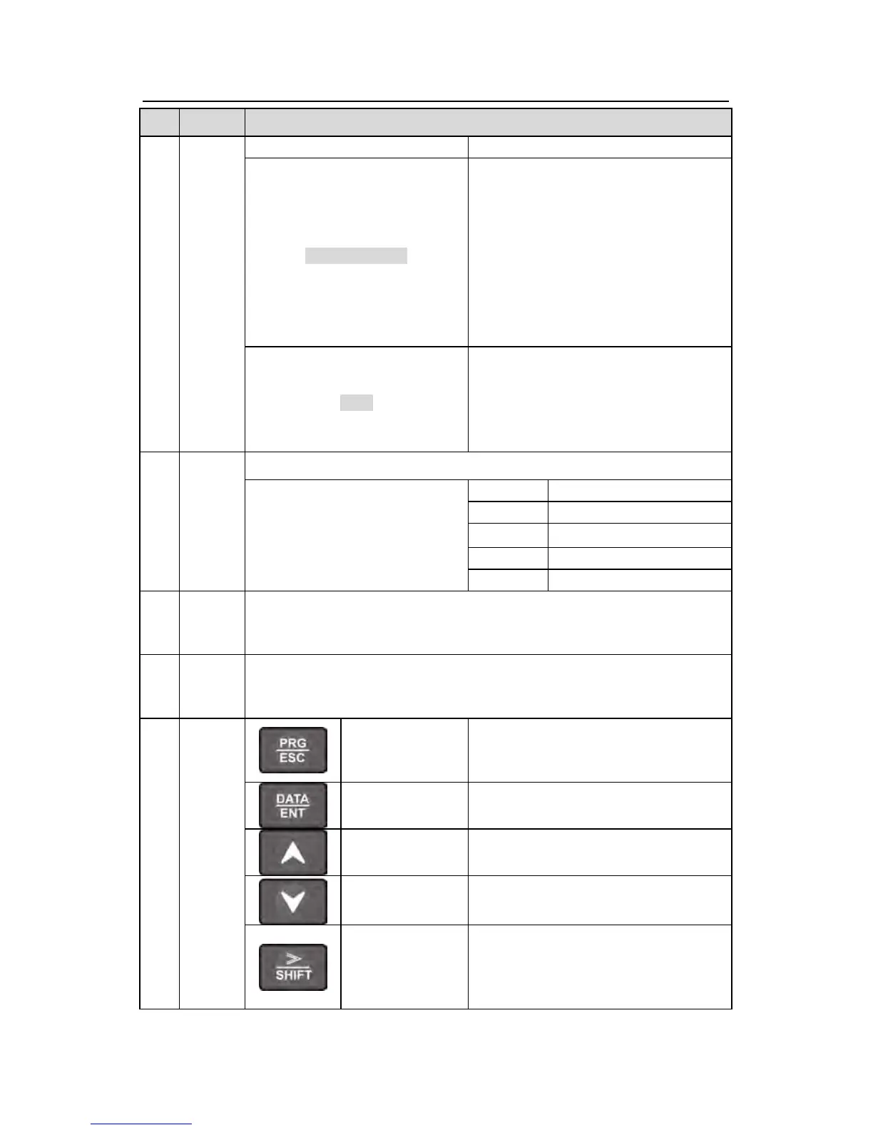
Description
state
LOCAL/REMOT
LED for keypad operation, terminals
operation and remote communication
control
LED off means that the inverter is in the
keypad operation state; LED blinking
means the inverter is in the terminals
operation state; LED on means the
inverter is in the remote communication
control state.
TRIP
LED for faults
LED on when the inverter is in the fault
state; LED off in normal state; LED
blinking means the inverter is in the
pre-alarm state.
2
Unit
LED
Mean the unit displayed currently
Hz Frequency unit
RPM Rotating speed unit
A Current unit
% Percentage
V Voltage unit
3
5-figure LED display displays various monitoring data and alarm code such
as set frequency and output frequency.
4
Tuning frequency. Please refer to P08.42.
5
Enter or escape from the first level
menu and remove the parameter
quickly
Entry key
Enter the menu step-by-step
Confirm parameters
UP key
Increase data or function code
progressively
DOWN key
Decrease data or function code
progressively
Right-shift key
Move right to select the displaying
parameter circularly in stopping and
running mode.
Select the parameter modifying digit