OFF
ON
Decelerate to stop
OFF
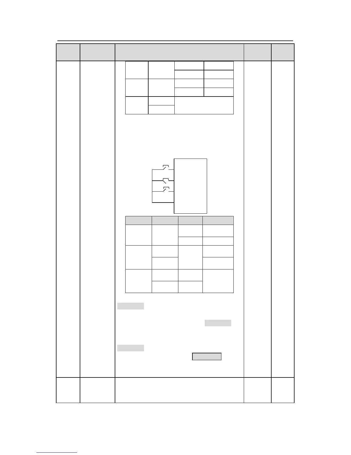
3:3-wire control 2; Sin is the enabling terminal on
this mode, and the running command is caused
by SB1 or SB3 and both of them control the
running direction.NC SB2 generates the stop
command.
COM
SB2
SB1
FWD
REV
SIn
SB3
Sln FWD REV Direction
Note: for the 2-wire running mode, when
FWD/REV terminal is valid, the inverter stop
because of the stopping command from other
sources, even the control terminal FWD/REV
keeps valid; the inverter won’t work when the
stopping command is canceled. Only when
FWD/REV is relaunched, the inverter can start
again. For example, the valid STOP/RST stop
when PLC signal cycles stop, fixed-length stop
and terminal control (see P07.04).
P05.14
The function code defines the corresponding
delay time of electrical level of the programmable
terminals from switching on to switching off.
0.000s