Goodrive18 series two-in-one VFD Communication
-118-
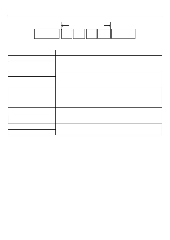
ASCII data frame format
Modbus message
Start character:
“0x3A”
Slave
address
Function
code
Data
Checkout
End character:
“0*0D”“0*0A”
Standard structure of an ASCII frame:
Communication address:
An 8-bit address is formed by the combination of two ASCII
codes.
Function code:
An 8-bit address is formed by the combination of two ASCII
codes.
Data content:
nx8-bit data content is formed by combination of 2n ASCII
codes.
n<=16, a maximum of 32 ASCII codes
LRC check code:
An 8-bit check code is formed by the combination of two
ASCII codes.
End character:
END Hi=CR (0x0D), END Lo=LF (0x0A)
ASCII mode check (LRC Check)
Check code (LRC Check) is the value combined of address and data content result.
The following is a simple LRC calculation function for your reference (using the C
programming language):
Static unsigned char
LRC(auchMsg,usDataLen)
unsigned char *auchMsg;
unsigned short usDataLen;
{
unsigned char uchLRC=0;
while(usDataLen--)
uchLRC+=*auchMsg++;
 Loading...
