Goodrive18 series two-in-one VFD Installing
-14-
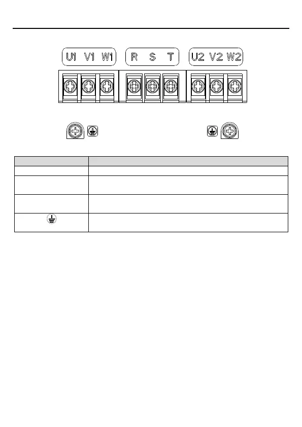
3.1.5 Main circuit terminal diagram
Figure 3.3 Main circuit terminal diagram
3PH AC input terminals, connected to the grid
First channel of 3PH AC output terminal, connected to the motor
in most cases
Second channel of 3PH AC output terminal, connected to the
motor in most cases
Protective earthing (PE) terminal for safe protection; each device
must be proper grounded.
Note:
Do not use asymmetrical motor cables. If there is a symmetrical grounding conductor in
the motor cable besides the conductive shielded layer, ground the grounding conductor on
the VFD end and motor end.
Route the motor cable, input power cable and control cables separately.
3.1.6 Wiring the main circuit terminals
Step 1 Connect the grounding line of the input power cable to the PE terminal of the VFD,
connect the 3PH input cable to the R, S and T terminals of the VFD, and tighten up.
Step 2 Connect the grounding line of the motor cable to the PE terminal of the VFD, connect
the 3PH cable of the motor to the U1/U2, V1/V2, and W1/W2 terminals of the VFD, and
tighten up.
Step 3 If allowed, fix all the cables at the outside of the VFD mechanically.

 Loading...