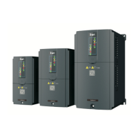
Goodrive18 series two-in-one VFD Installing
-17-
Output range: 0–10V or 0–20mA
Whether the terminals use voltage
or current as output is set through
the dial switch.
Full range deviation: ±1%, 25°C
RO1 output: RO1A is NO, RO1B is
NC, and RO1C is the common
terminal.
RO2 output: RO2A is NO, RO2B is
NC, and RO2C is the common
terminal.
Contact capacity: 3A/AC250V
Common
terminal of
relay 1
Common
terminal of
relay 2
3.1.9 Input/output signal connection diagram
Please use the jumper to set the NPN mode or PNP mode and select the internal or external
power supply. The default setting is the NPN internal mode. The 22AWG wire diameter is
recommended for external wiring.

 Loading...