Goodrive18 series two-in-one VFD Installing
-16-
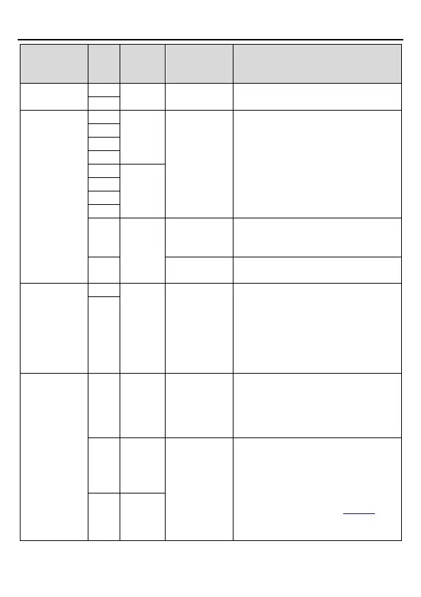
RS485 communication terminals, using
the MODBUS protocol
Internal impedance: 3.3kΩ
12–30V voltage input is acceptable
Bi-direction input terminals
Max. input frequency: 1kHz
Used to provide the working power
supply for digital from the external
Voltage range: 12–30V
Common terminal of open collector
output
Used to provide the 24V±10% power
supply for the external. Max. output
current: 200mA
Generally used as the digital
input/output working power supply or
externally connected to the sensor
power supply
External 10V
reference
power supply
10V reference power supply. Max.
output current: 50mA
Generally used as the adjusting power
supply of the external potentiometer with
the resistance of higher than 5kΩ
Input range: For AI2, 0–10V or 0–
20mA. For AI3, -10V–+10V
Input impedance: 20kΩ for voltage
input or 500Ω for current input
Whether AI2 uses voltage or current
as input is set through P05.49.
Resolution: 10mV/20mV for AI2/AI3
when 10V corresponds to 50Hz
 Loading...
