Goodrive18 series two-in-one VFD Operating
-21-
4 Operating
4.1 Keypad introduction
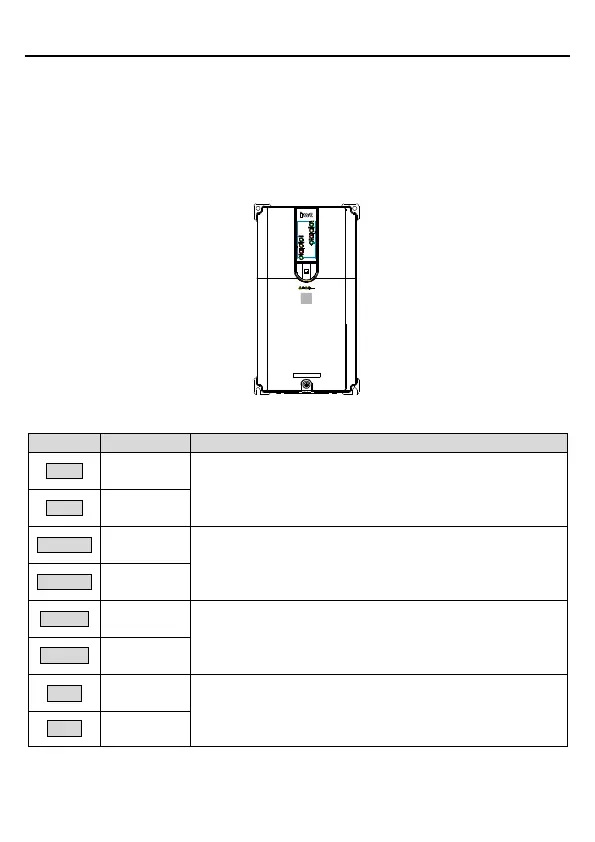
Goodrive18 series two-in-one VFD does not provide a keypad but contains eight indicators, as
shown in Figure 4.1. You need to use an external keypad (optional part) for parameter
commissioning and use a standard RJ45 network cable to connect the external keypad to the
VFD.
Figure 4.1 Indicators
Running status indicator.
On: The inverter unit is running.
Off: The inverter unit is stopped.
Ready-to-run indicator.
On: The inverter unit is ready to run.
Off: The inverter unit is running.
Fault indicator.
On: The inverter unit is in fault state.
Off: The inverter unit is in normal state
Blinking: The inverter unit is in pre-alarm state.
Operation object indicator, identifying which inverter unit the
external keypad works on.
KEY1 on but KEY2 off: The keypad works on #1 inverter unit.
KEY1 off but KEY2 on: The keypad works on #2 inverter unit.

 Loading...