Goodrive18 series two-in-one VFD Installing
-13-
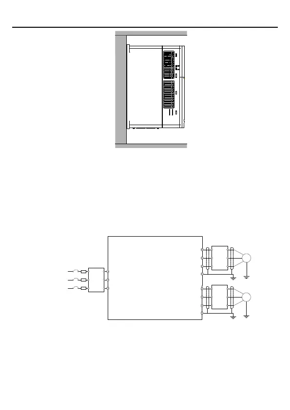
Figure 3.1 Installation method
Step 1 Mark the positions of the installation holes. For details about the positions, see
Appendix B "Dimensional drawing".
Step 2 Mount the screws or bolts onto the marked positions.
Step 3 Place the VFD against the wall.
Step 4 Fasten the screws on the wall.
3.1.4 Main circuit wiring diagram
R
S
T
W1
V1
U1
PE
M1
Input
reactor
Input
filter
Fuse
Output
reactor
Output
filter
380V 0.75~7.5kW
3PH power
380V(-15%)~
440V(+10%)
50/60Hz
W2
V2
U2
PE
M2
Output
reactor
Output
filter
Figure 3.2 Main circuit wiring diagram
Note: The fuse, input reactor, input filter, output reactor, and output filter are optional parts. For
details, see Appendix C "Optional peripheral accessories".

 Loading...