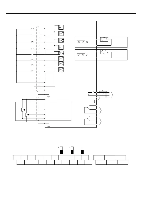
EasyManuals Logo

INVT Goodrive18 Series User Manual

INVT Goodrive18 Series
157 pages
To Next Page IconTo Next Page
To Previous Page IconTo Previous Page
Page #20 background imageLoading...
Page #20 background image
Goodrive18 series two-in-one VFD Installing
-15-
3.1.7 Control circuit wiring diagram
(External) -10V
Shield
layer
Twisted
pair
Multifunction input terminal 1
Multifunction input terminal 2
Multifunction input terminal 3
Multifunction input terminal 4
Multifunction input terminal 5
Multifunction input terminal 6
Multifunction input terminal 7
Multifunction input terminal 8
Open collector input is optional
+10V power for frequency setting
+24V
PE
AI3 multifunction analog input
AI2
GND
PE
COM
PW
Relay 1 output
Relay 2 output
RS485
communication
Analog output
0-10V/0-20mA
Analog output
0-10V/0-20mA
S1
S2
S3
S4
S5
S6
S7
S8
AO1
GND
GND
AO2
485+
485-
GND
J5
PE
RO1A
RO1B
RO1C
RO2A
RO2B
RO2C
J6
V
I
J7
V I
Voltage or current
output, set through
P05.49
Figure 3.4 Control circuit wiring diagram
3.1.8 Control circuit terminal diagram
ON
AO1 AO2
485
S1 S2 S3 S4 AI2
AI3
RO1A RO1B RO1C
RO2A RO2B RO2C
PW COM COM
AO1
485+
V V
AO2
485-
GND
S5 S6 S7 S8 +24V
+10V
Figure 3.5 Control circuit terminal diagram

Table of Contents

Questions and Answers:

Question and Answer IconNeed help?

Do you have a question about the INVT Goodrive18 Series and is the answer not in the manual?

INVT Goodrive18 Series Specifications

General IconGeneral
BrandINVT
ModelGoodrive18 Series
CategoryIndustrial Electrical
LanguageEnglish

Related product manuals