Goodrive18 series two-in-one VFD Operating
-23-
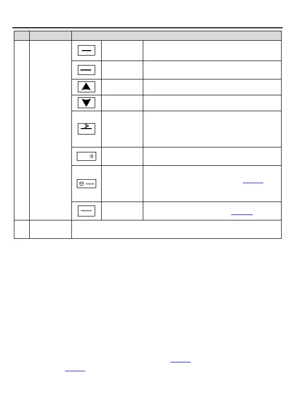
Press it to enter or exit level-1 menus or delete
a parameter.
Press it to enter menus in cascading mode or
confirm the setting of a parameter.
Press it to increase data or move upward.
Press it to decrease data or move downward.
Press it to select display parameters rightward
in the interface for the device in stopped or
running state or to select digits to change
during parameter setting.
Press it to run the device when using the
keypad for control.
Press it to stop the device that is running. The
function of this key is restricted by P07.04. In
fault alarm state, this key can be used for reset
in any control modes.
Multifunction
shortcut key
The function is determined by P07.02.
4.2 Keypad display
The external keypad for operating Goodrive18 series two-in-one VFD displays the
stopped-state parameters, running-state parameters, function parameter editing status, and
fault alarm status. Goodrive18 series two-in-one VFD has two channels of inverting output,
which are distinguished by the prefix letters P/F. Function codes in group P correspond to the
output (U1/V1/W1) of #1 inverter unit, while function codes in group F correspond to the output
(U2/V2/W2) of #2 inverter unit. The setting methods of the two groups of function code are the
same. The following describes only the function codes in group P.
4.2.1 Displaying stopped-state parameters
When the VFD is in stopped state, the keypad displays stopped-state parameters.
In the stopped state, various kinds of parameters can be displayed. You can determine which
parameters are displayed by setting the binary bits of P07.07. For definitions of the bits, see
the description of P07.07.
In stopped state, there are 15 parameters that can be selected for display, including set

 Loading...