P05.32 setting range: 0.00V–P05.34
P05.33, P05.35 setting range: -100.0%–100.0%
P05.34 setting range: P05.32–10.00V
P05.36 setting range: 0.000s–10.000s
P05.37 setting range: 0.00V–P05.39
P05.38, P05.40 setting range: -100.0%–100.0%
P05.39 setting range: P05.37–10.00V
P05.41 setting range: 0.000s–10.000s
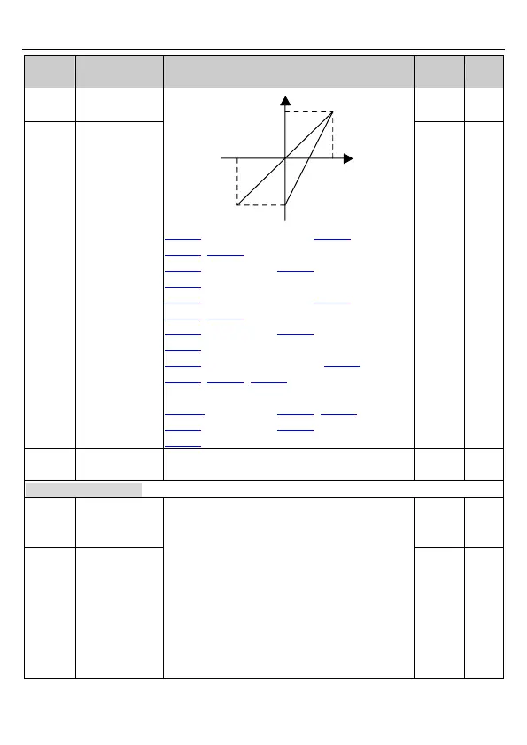
P05.42 setting range: -10.00V–P05.44
P05.43, P05.45, P05.47 setting range: -100.0%–
100.0%
P05.44 setting range: P05.42–P05.46
P05.46 setting range: P05.44–10.00V
P05.48 setting range: 0.000s–10.000s
Note: By default, RO1 is assigned to #1 inverter
unit, and RO2 is assigned to #2 inverter unit. If
you want to change the configuration, see
section 5.2 for details.
0: Invalid
1: Running
2: Forward rotation
3: Reverse rotation
4: Jogging
5: VFD fault
6: Frequency level test FDT1

 Loading...