Goodrive18 series two-in-one VFD Installing
-18-
+24V and PW are short connected through the jumper
Figure 3.6 Jumper based short connection
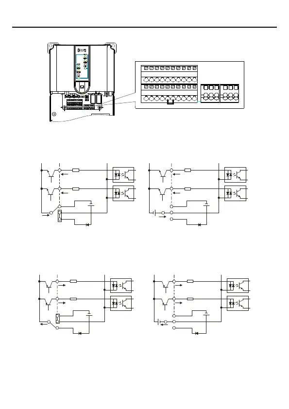
If the input signal comes from NPN transistor, set the jumper according to the used power
supply.
S1
S2
COM
PW
+ 24V
COM
+24V
Internal power supply (NPN mode)
S1
S2
COM
PW
+ 24V
COM
+24V
+ 24V
External power supply (NPN mode)
Figure 3.7 NPN mode
If the input signal comes from PNP transistor, set the jumper according to the used power
supply.
S1
S2
COM
PW
+ 24V
COM
+24V
S1
S2
COM
PW
+ 24V
COM
+24V
Internal power supply (PNP mode)
External power supply (PNP mode)
Figure 3.8 PNP mode

 Loading...