Goodrive18 series two-in-one VFD Communication
-136-
Parameters
address
CRC check
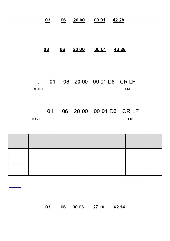
VFD
address
Write
command
Forward
running
If the operation is successful, the following response is returned (same as the command sent
from the master):
Parameters
address
CRC check
VFD
address
Write
command
Forward
running
ASCII mode
The command sent from the master is as follows:
Parameters
address
VFD
address
Write
command
LRC
check
Data
number
If the operation is successful, the following response is returned (same as the command sent
from the master):
Parameters
address
VFD
address
Write
command
LRC
check
Data
number
Example 2: Set the max. output frequency to 100 Hz for the VFD with the address of 03H.
Used to set the max. output frequency of
the VFD. It is the basis of frequency setup
and the acceleration/deceleration.
Setting range: P00.04–400.00 Hz
See the figures behind the radix point, the fieldbus ratio value of max. output frequency
(P00.03) is 100. 100Hz timed by 100 is 10000 and the corresponding hex is 2710H.
RTU mode
The command sent from the master is as follows:
Parameters
address
VFD
address
Write
command
CRC check Forward running

 Loading...