EasyManuals Logo

INVT Goodrive18 Series User Manual

INVT Goodrive18 Series
157 pages
To Next Page IconTo Next Page
To Previous Page IconTo Previous Page
Page #15 background imageLoading...
Page #15 background image
Goodrive18 series two-in-one VFD Product overview
-10-
2
4
3
1
11
10
5
6
7
8
9
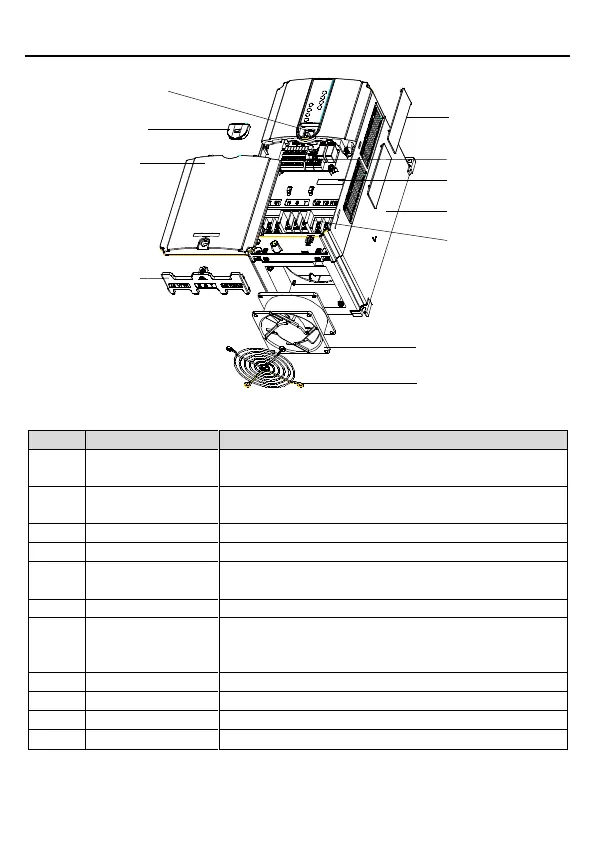
Figure 2.3 Structural diagram
No.
Item
Description
1
External keypad
interface
Used to connect an external keypad.
2
External keypad
interface cover
Used to protect the external keypad interface.
3
Lower cover
Used to protect the internal components.
4
Junction box
Used to fix the cables of the main and control circuits.
5
Ventilation hole
cover
Used to prevent against the ingress of dust or water.
6
Control terminals
See "Installing".
7
Barcode label
Same as the barcode on the nameplate.
Note: The barcode identified by 7 is located in the middle
of the housing and can be seen after the cover is removed.
8
Nameplate
See "Product nameplate".
9
Main circuit terminals
See "Installing".
10
Cooling fan
See "Troubleshooting".
11
Fan cover
Used to protect the fan.

Table of Contents

Questions and Answers:

Question and Answer IconNeed help?

Do you have a question about the INVT Goodrive18 Series and is the answer not in the manual?

INVT Goodrive18 Series Specifications

General IconGeneral
BrandINVT
ModelGoodrive18 Series
CategoryIndustrial Electrical
LanguageEnglish

Related product manuals