Single Phase Hybrid Inverter Electrical Connection
18
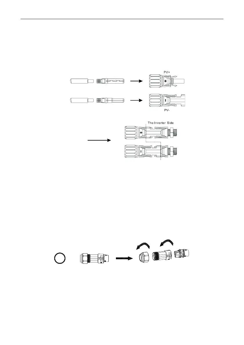
5.2 PV Wiring
MC4 connectors are provided at DC input side of the hybrid inverter. Below are the connection steps.
1. Turn off the DC switch.
2. Connect the positive terminal and negative terminal of the PV module respectively to the PV+ port and PV-
port of the hybrid inverter. Make sure the actual input voltage and current fall within the allowable range.
●
Maximum allowable PV input voltage: 600V (please consider changes in the voltage at the minimum
temperature).
●
Maximum allowable PV input current: 16A.
Note: It is recommended to use a specialized PV cable ≥4mm² (11AWG).
5.3 AC Wiring
The AC output side is located at the bottom right of the hybrid inverter, containing an EPS port on the left and
a GRID port on the right (see Chapter 3 Product Introduction for detailed information).
Step 1: Unscrew the AC terminal, and then use an appropriate tool to remove it as shown below.
Step 2: Pass the cable through the rubber nut, sealing ring and threaded sleeve in turn. Connect the cable to the
corresponding terminal based on the polarity mark, and then tighten the threaded sleeve onto the AC terminal as
shown below:

 Loading...