INSTRUMENTS & CONTROLS
29
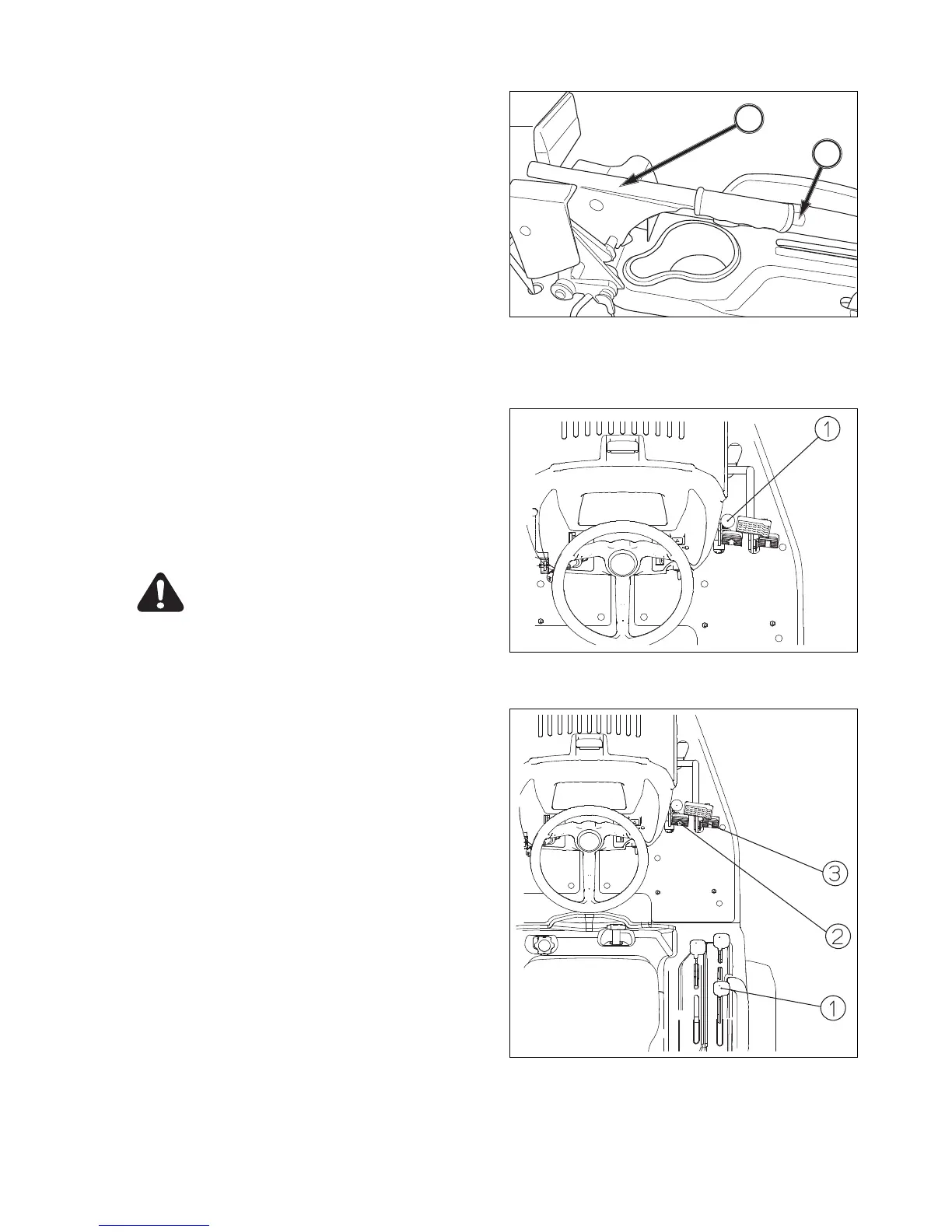
FIG. 3-12
FIG. 3-13
FIG. 3-14
Parking Brake
To apply parking brakes, pull upward on parking lever,
2, to lock brakes in applied position.
To disengage parking brakes, push in on release but-
ton, 3, and lower lever to the released position.
IMPORTANT: Always disengage brake before driving
tractor to prevent abnormal brake wear
ENGINE SPEED CONTROLS
Throttle Lever
FIG. 3-13: Throttle lever, 1, controls engine speed and
will remain in position selected by the operator.
Idling speed: With hand lever is rearward, engine
will idle.
High speed: Engine speed increases as lever is
moved forwarded progressively.
CAUTION: Always select engine speed
to ensure safe operation. Reduce speed
prior to turning or backing Tractor.
TRANSMISSION SHIFT LEVER AND CONTROLS
FIG. 3-14: One shift lever is used to select a range of
ground travel speed through different gear reductions
within the drive train. A hydrostatic control unit allows
infinitely variable speeds, from zero to top speed, in
each range.
Range Gearshift Lever, 1, is located to right of
operator’s seat, range lever provides 2 major speed
changes. This lever has “tortoise” and “hare” positions
with neutral at center.
IMPORTANT: Tractor must be completely stopped
when shifting.
Hydrostatic Control Pedal, 2 & 3, Located on right
side of platform and it actuates hydrostatic unit in for-
ward or reverse travel direction.
Depressing forward portion of pedal moves Tractor
forward, depressing rearward portion of pedal moves
Tractor rearward. As each movement is progressively
depressed, a corresponding increase in ground speed
of Tractor will be noticed in appropriate direction.
2
3