MAINTENANCE & ADJUSTMENT
69
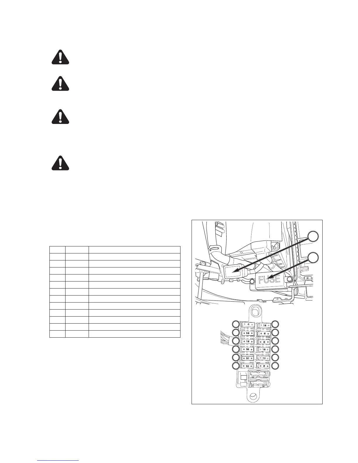
FIG. 5-35
Wiring/Fuse Arrangement
CAUTION: Keep all wiring connections
clean and tight. Make sure wiring is cor-
rectly secured to prevent damage.
CAUTION: DO NOT alter wiring by adding
“homemade” extensions or replacements.
Doing so can eliminate fuse protection and/
or eliminate safety features of the system.
CAUTION: Tractor is equipped with nega-
tive (-) ground system. Tractor metal parts
provide many electrical connections. For
this reason, all positive (+) circuits must
be insulated to prevent “grounding” or
short circuits and prevent possible fire.
CAUTION: DO NOT replace any fuse with
a fuse of higher amperage rating. DO NOT
use wire (or foil) to bypass fuse protec-
tion. Fire can result.
If fuses blow repeatedly, examine electrical system for
“grounded” or “shorted” circuits.
FUSE / Head Light
FIG. 5-35: Main Fuse Box, A-Located on right side, to
rear of engine.
TABLE 10
Ref. Rating Function
1. 20A POWER SUPPLY CAB (B)
2. 15A LAMP / HORN
3. 15A HEAD LAMP
4. 15A BRINCER
5. 10A STOP LAMP
6. 10A ENGINE STOOP SOLENOID
7. 15A POWER SUPPLY (ACC)
8. 5A ACC / FUEL PUMP
9. 10A GLOW MONITER
10. 15A SPARE
11. 10A SPARE
12. 10A SPARE
Slow-Blow Fuses, - In-line fuses protect relevant
circuit by melting when sustained heavy electrical
load or short circuit is encountered. Feature a delayed
action to prevent current disruption when brief surges
are encountered.
(40A) slow-blow fuse, for main circuit is green in color.
Fuse is located on right side of battery.
B
A
1
2
3
4
5
6
7
8
9
10
11
12
TOOL
(
FUSE)