TXG237
46
Using Position Control
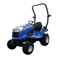
FIG. 4-19: Type of Work - Attaching/detaching imple-
ments and other operations requiring implement to be
kept at constant height above ground. Also used with
implements equipped with gauge (support) wheels.
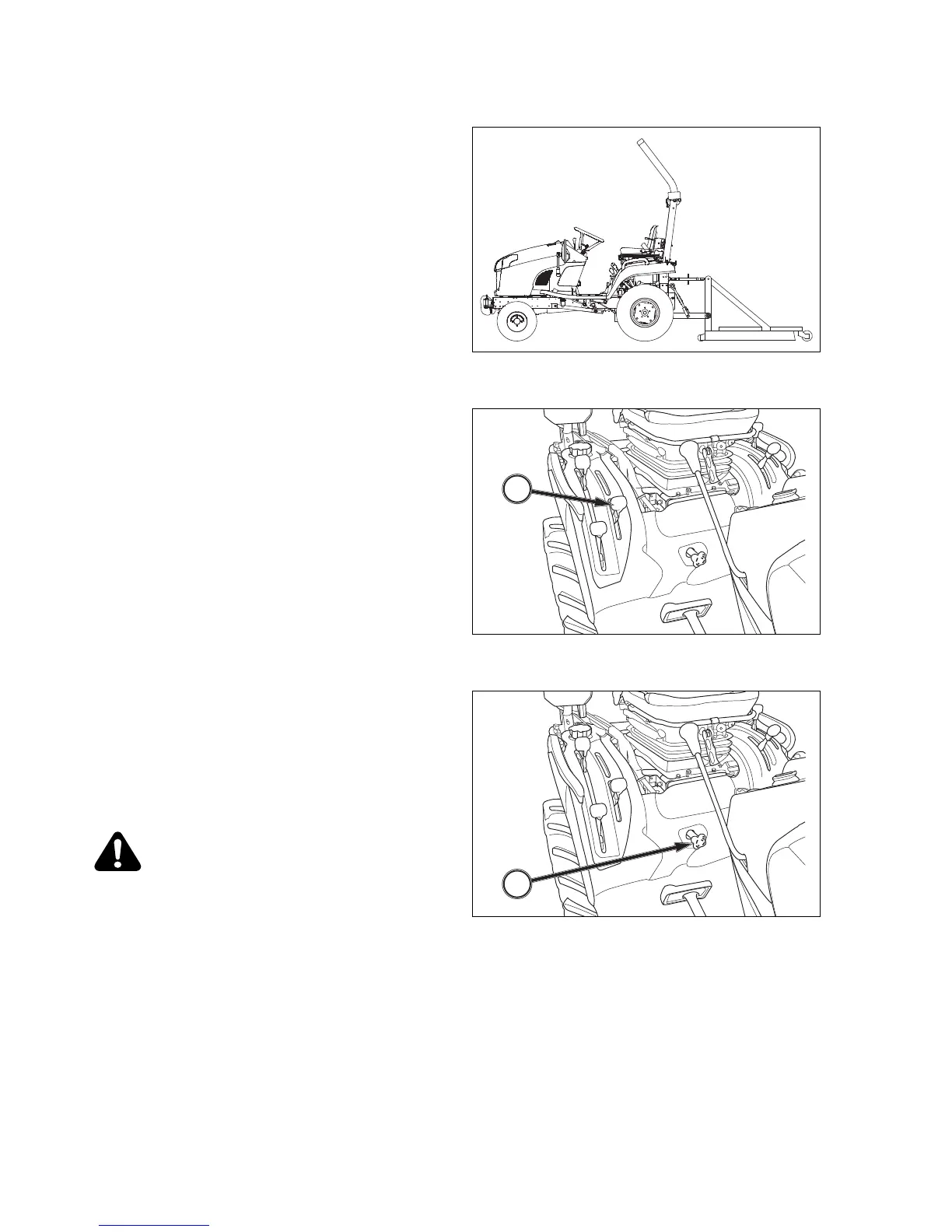
FIG. 4-20: Lever Positions - Use position control lever,
1, to adjust hitch and implement position.
To Begin Work - Align Tractor and implement in field
and move position control lever, 1, forward (toward
DOWN). Adjust implement height using position con-
trol lever as desired. Note location of lever.
When Turning - Move position lever, 1, rearward (to-
ward UP) to raise implement. Finish turning and return
lever to previously set position to resume operation.
To Finish Work and Transport - Move position control
lever, 1, fully rearward in quadrant.
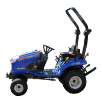
FIG. 4-21: When using different weights of implements,
“rate of drop” of 3 point linkage and implement can be
controlled with the “Lowering Rate Control” Knob, 1.
Turn knob clock wise to slow drop rate, counterclock-
wise to increase drop rate. Turning knob fully clock-
wise will lock implement in raised position.
CAUTION: When using mounted imple-
ments with the PTO driveline, make sure:
PTO drive shaft has minimum 51mm en-
gagement of telescoping sections, at all
hitch/implement positions.
Hitch height during raising does not bind
drive shaft universal joints due to extreme
drive shaft length,
PTO drive is disengaged during transport.
1
1
FIG. 4-19
FIG. 4-21
FIG. 4-20