Inspection and Installation
1. Confirm that the power switch is in the OFF position and verify that there is
no dangerous voltage on the connection terminals.
2. Remove the output terminals cover of the power supply.
3. Loosen the screws of the output terminals and connect the red and black
test cables to the output terminals. Re-tighten the screws.
When maximum current that one test cable can withstand fails to meet the
rated current, use multiple pieces of red and black test cables. For example,
the maximum current is 1,200A, then 4 pieces of 360A red and black cables
are required.
4. Thread the red and black test cables through the output terminals cover of
the power supply and install the cover.
5. (Optional) According to the actual situation of DUT, connect the grounding
terminal on the rear panel of the instrument to the DUT to ensure the safe
grounding.
For the location information, see 1.5 Rear Panel Introduction.
6. Connect the other end of the red and black cables to the DUT. The positive
and negative poles must be properly connected and fastened when wiring.
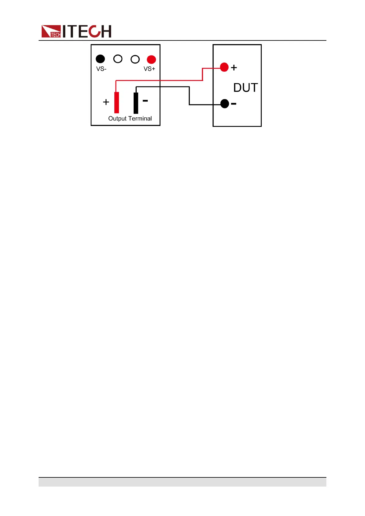
Connecting the DUT (Remote Sensing)
Remote measurement is available for the following scenarios:
When the DUT consumes large current or the wires are too long, there is a volt-
age drop on the wires between DUT and output terminals of the power supply.
To maximize measurement accuracy, the power supply provides the remote
measurement terminals VS+ and VS- on the rear panel, which can be used to
measure the terminal voltage of the DUT.
When the power supply is used for battery testing in actual applications, the
voltage drop of the wire will lead to voltage inconsistency of both ends and in-
consistency of the cutoff voltage of power supply and the actual voltage of bat-
tery, resulting in inaccurate measurement.
The connection diagram and steps of remote measurement are as follows:
Copyright © Itech Electronic Co., Ltd.
29

 Loading...


