Inspection and Installation
1. Confirm that the power switch is in the OFF position and verify that there is
no dangerous voltage on the connection terminals.
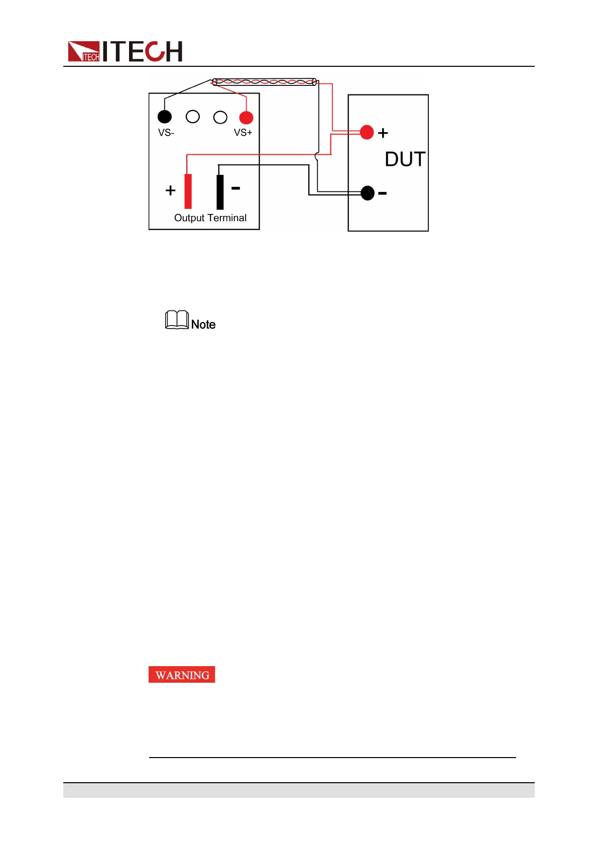
2. Refer to the wiring diagram and connect the Vs+ and Vs- with armored
twisted-pair cables.
To ensure the stability of the system, use armored twisted-pair cables be-
tween the remote sense terminals and the DUT. Pay attention to the posi-
tive and negative poles when wiring, otherwise it will damage the
instrument.
3. Remove the output terminals cover of the power supply.
4. Loosen the screws of the output terminals and connect the red and black
test cables to the output terminals. Re-tighten the screws.
When maximum current that one test cable can withstand fails to meet the
rated current, use multiple pieces of red and black test cables. For example,
the maximum current is 1,200A, then 4 pieces of 360A red and black cables
are required.
5. Thread the red and black test cables through the output terminals cover of
the power supply and install the cover.
6. (Optional) According to the actual situation of DUT, connect the grounding
terminal on the rear panel of the instrument to the DUT to ensure the safe
grounding.
For the location information, see 1.5 Rear Panel Introduction.
7. Connect the other end of the remote sense cables to the DUT.
8. Connect the other end of the red and black cables to the DUT. The positive
and negative poles must be properly connected and fastened when wiring.
9. Power on the instrument and turn on the Sense function of the instrument.
For details, see 5.7 Sense Function (Sense).
Never touch cables or connections immediately after turning off
the instrument at the end of the test. Lethal voltages may remain
at the output terminals after turn-off. Verify that there is no dan-
gerous voltage on the output or sense terminals before touching
them.
Copyright © Itech Electronic Co., Ltd.
30

 Loading...


