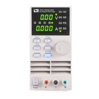
Remote Control
Copyright © Itech Electronic Co., Ltd. 10
calibration (none, even, odd)
EVEN 8 data bits, have even parity
ODD 8 data bits have odd parity
NONE 8 data bits, no parity
Local Address: (0 ~ 31, the factory default setting is 0)
USB interface
Use a Cable with two USB port to connect the power and the computer. All
power functions can be programmed via USB.
The USB488 interface functions of the power supply described as below:
⚫ Interface is 488.2 USB488 interface.
⚫ Interface Receiver REN_CONTROL, GO_TO_LOCAL, and
LOCAL_LOCKOUT request.
⚫ Interface Receive MsgID = TRIGGER USBTMC order information, and will
pass TRIGGER order to the functional layer.
Power USB488 device functions described as follows:
⚫ Devices can read all of the mandatory SCPI orders.
⚫ Device is SR1 enabled.
⚫ Device is RL1 enabled.
⚫ Device is DT1 enabled.
RS485 interface
IT6726C power supply, via the RS485 interface, provides multi-unit control
function for up to 30 units (If connecting more than 10 units, add a 120Ω
resistor terminator to the last unit as shown in the figure below). Access the
menu tree Menu → SYST SET → COMM → RS485 to set the RS485
settings.
User can set the following parameters of the RS485 interface:
Baud Rate: 9600(4800/9600/19200/38400/57600/115200)
Parity and data bit: NONE/8BIT、EVEN/8BIT、ODD/8BIT
MODE:SIGNAL、MUX
SIGNAL(single-unit mode)
MUX(multi-unit mode), ADDR(Address),( 0~30,the factory default
setting is 0)
To set the multi-unit connection mode, access the menu tree MENU →SYST
SET → COMM → RS485 → MODE → MUX to choose the multi-unit mode.
Set each unit with a different Address (0 ~ 30). Then by using RS485 connect
the first power supply in the chain to a PC. Now, multiple units daisy-chained
via RS485 can be controlled by one PC by using the commands specific for
multi-unit connection. See “Programming Guide” section for details.
ООО "Техэнком" Контрольно-измерительные приборы и оборудование www.tehencom.com