EasyManuals Logo

ITRON ACE6000 User Manual

ITRON ACE6000
85 pages
To Next Page IconTo Next Page
To Previous Page IconTo Previous Page
Page #16 background imageLoading...
Page #16 background image
ACE6000 User Guide
14
Excess energy
Power factor aggregate quantity
RMS voltage and current per phase quantity
Frequency
Ambient temperature
Alarm status
Power factor per phase
Incremental data
Communication
RS232 or RS485
DLMS-Cosem compliant
PSTN, LAN (TCP/IP), GSM and GPRS media supported
Network quality monitoring
Voltage cuts, sags and swells
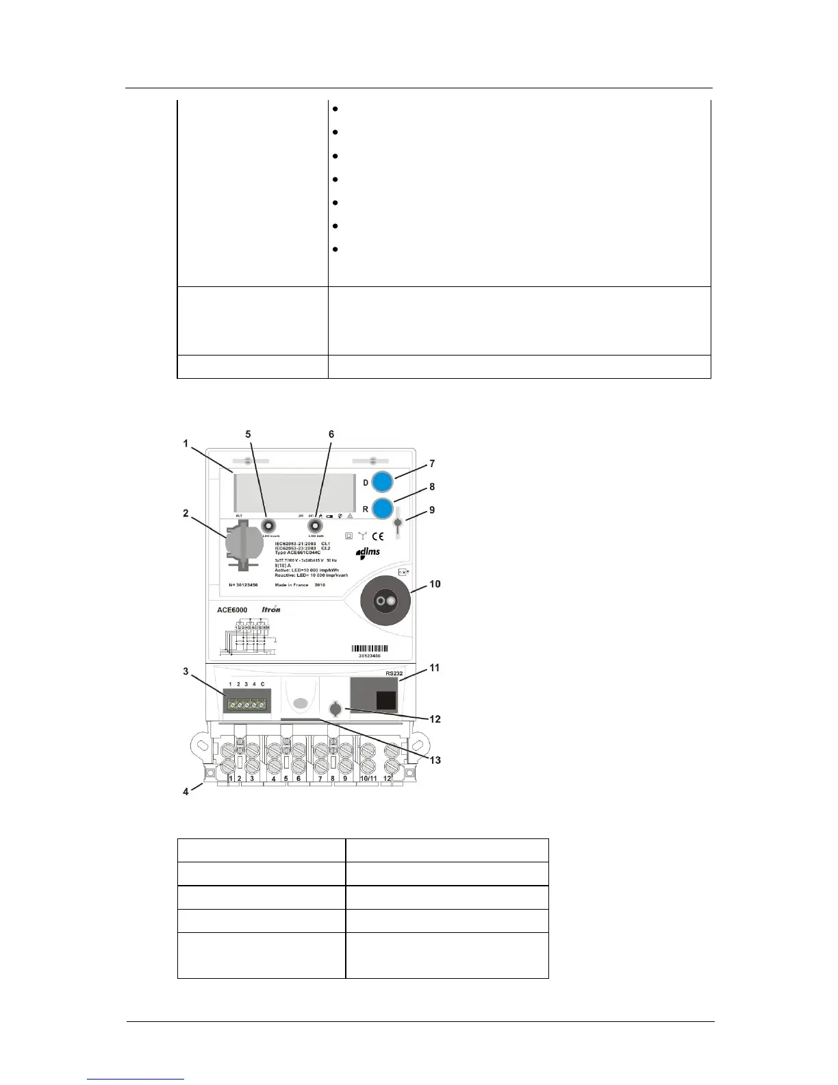
The diagram below shows the main functional elements of the meter:
1
Liquid crystal display (LCD)
2
Battery holder
3
Control output terminal block
4
Main wiring terminal block
5
Reactive power metrology LED (kvarh)
6
Active power metrology LED (kWh)
7
Display pushbutton
8
Reset pushbutton
9
Hinged front cover latch
10
Infrared communication port
11
Serial communication port
12
Terminal cover switch
13
Read without power (RWP) battery holder
(optional)
5.2. General specifications
Frequency
50/60 Hz
Connection wiring
3 or 4 wire
Connection configuration
Direct or Transformer
Terminal wiring
VDE (asymmetrical)
Real Time Clock backup
Field-replaceable battery and
Internal super-capacitor

Table of Contents

Questions and Answers:

Question and Answer IconNeed help?

Do you have a question about the ITRON ACE6000 and is the answer not in the manual?

ITRON ACE6000 Specifications

General IconGeneral
Voltage230V AC
Frequency50/60 Hz
DisplayLCD
CommunicationRS-485
Temperature Range+55°C
Current5A
Frequency Range45Hz to 65Hz
Storage Temperature+70°C
Humidity95% RH (non-condensing)

Related product manuals