EasyManua.ls Logo

ITRON ACE6000 User Manual

ITRON ACE6000
85 pages
To Next Page IconTo Next Page
To Previous Page IconTo Previous Page
Page #43 background imageLoading...
Page #43 background image
Erreur ! Utilisez l'onglet Accueil pour appliquer Heading 1 au texte que vous souhaitez faire apparaître ici.
Sliding mode
In the sliding mode the demand period is divided into between 1 and 15 fixed integration periods. The total
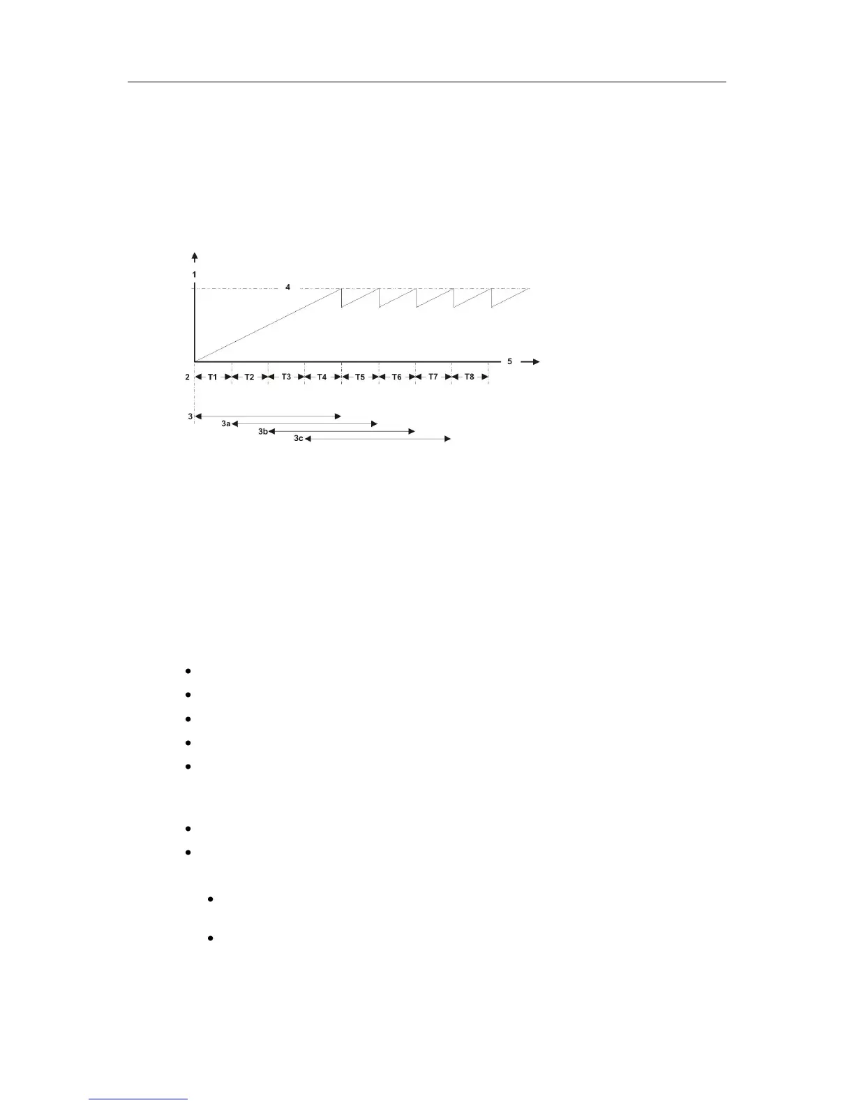
maximum duration of a sliding demand period is 15 (maximum periods) x 60 (maximum minutes) = 900 minutes.
The illustration below shows a sliding mode demand period comprising 4 integration periods with, for example a
duration of T = 5 minutes. The sliding demand period total duration = 20 minutes with the rising demand value
based on a constant load:
1
Rising value
2
Integration periods
3
First sliding period
3a
Second sliding period
3b
Third sliding period
3c
Forth sliding period
4
Actual demand value
5
Elapsed time
At the end of each completed integration period (T) the demand value is calculated and temporarily stored.
At the end of the first sliding period (3), an average demand value based on the results from all integration
periods within that sliding period (T1,T2,T3,T4), is calculated.
When the next integration period (T5) ends, a new average demand value based on the results of integration
periods (T2,T3,T4,T5), is calculated.
This process is then repeated at the end of every successive integration period until an end of billing event
occurs.
7.10.4.4. Demand calculation
At the end of each integration period (EOI), the meter calculates the following:
average demand over the integration period
average three-phase power factor over the integration period
minimum power factor - the meter records the lowest values in the current billing period
average power factor over the current billing period
maximum demand coincident values - if enabled
If coincident values is set on channel 1 and a maximum demand is recorded, the demand on the last
channel is also recorded (even if a maximum demand is not detected on that channel)
cumulative maximum demand - the meter records this value over the current billing period
maximum demand - the meter records the 3 highest peaks in the current billing period.
The meter offers two maximum demand modes (applied across all channels):
Maximum mode - this default mode registers the maximum demand peaks only, any preconfigured
thresholds will be ignored.
Maximum Excess mode - this mode activates the preconfigured thresholds. If a threshold is defined for
a channel, only the maximum demand peak value above the threshold is recorded. If no threshold is
defined the operation is identical to Maximum mode (as above).

Table of Contents

Question and Answer IconNeed help?

Do you have a question about the ITRON ACE6000 and is the answer not in the manual?

ITRON ACE6000 Specifications

General IconGeneral
Voltage230V AC
Frequency50/60 Hz
DisplayLCD
CommunicationRS-485
Temperature Range+55°C
Current5A
Frequency Range45Hz to 65Hz
Storage Temperature+70°C
Humidity95% RH (non-condensing)

Summary

Safety Information

Meter Handling Safety

Precautions for safely isolating and handling meters before installation or removal.

Installation Safety Precautions

Guidelines for safe meter installation, including isolation and circuit protection.

Transformer Connection Safety

Safety advice for working with meters connected to Voltage and Current Transformers.

Technical Description

Metrology

Description of the meter's integral Mutual Conductance Transformers and signal processing.

Measurement Error Correction

How meters can be configured to correct for measurement errors from CT/VT.

Power-Fail Operation

How meter data is saved in non-volatile memory during power outages.

Backup Power Supply

Details on the super-capacitor and optional lithium battery for power backup.

Reading Without Power (RWP)

Feature allowing meter reading during main network power loss using dedicated batteries.

Metered Quantities Overview

Introduction to the various energy values measured by the meter.

Four Quadrant Metering

Measurement of energy values in all four quadrants of the AC waveform.

Measured Energy Quantities Details

Details of active and reactive energy quantities recorded by the meter.

Demand Registering Overview

Monitoring energy demand limitations and threshold parameters.

Demand Integration Period

Programmable duration and modes (fixed/sliding) for calculating demand.

Demand Calculation Methods

How the meter calculates demand, including maximum demand modes.

End of Integration (EOI) Triggers

Sources that can trigger an end of integration period (EOI) event.

Excess Demand Handling Modes

Modes for detecting and indicating excess demand above predefined thresholds.

Network Quality Monitoring

Monitoring distribution-network voltage-quality parameters like cuts, sags, and swells.

Fraud Protection and Tamper Detection

Features designed to prevent tampering and detect attempted fraud.

Magnetic Field Detection and Anti-Tamper

Optional sensor for detecting magnetic fields used in anti-tamper attempts.

Alarm and Event Management

Overview of how the meter manages alarms and records events.

Meter Logbook Contents

List of selectable logbook events for recording metering events.

Alarm Types and Classification

Classification of alarms as Fatal or Non-fatal and their clearing methods.

Alarm Notification Methods

Ways alarms are reported, including LCD display, control output, and SMS/email.

Installation

General Installation Warnings

Mandatory safety requirements before and during meter installation.

Battery Installation and Replacement

Procedure for safely installing or replacing the meter's lithium battery.

Pre-Installation Checks

Checks to be performed before connecting the mains supply to the installed meter.

Start-up and Functional Testing

Steps to check meter functionality after installation and connection.

Meter Sealing Procedures

How to seal the meter terminal cover against unauthorized access.

Technical Appendix

Detailed Alarm Descriptions

Descriptions and classifications for various non-fatal and fatal alarms.

Related product manuals