LCD
menu
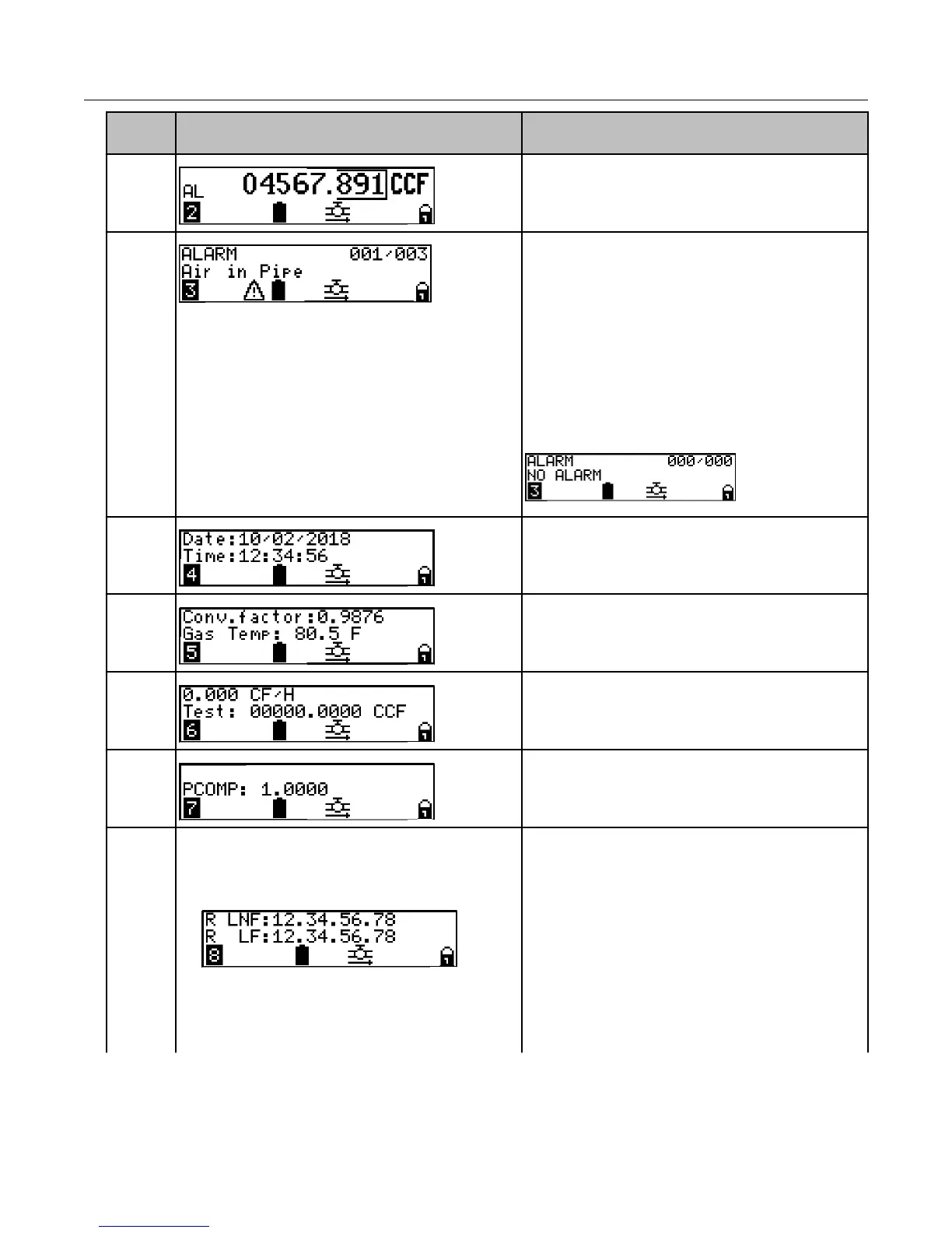
LCD display Description
2. Displays current index volume measured
under an alarm condition.
3. Displays active alarms.
Note: In the illustration, 001 indicates the
number of the current displayed alarm while
003 indicates the total number of alarms.
Before the display moves to the next menu
page, all active alarms are displayed. If
there are no alarms, NO ALARM
displays.
For more information about the Intelis Gas
Meter display events and alarms, see Intelis
Gas Meter LCD display alarms on page 17.
4. Local date and time. The local date is
formatted as configured. The date and time
are adjusted by the local time zone and DST
configuration.
5. Current gas temperature and conversion
factor
. This is the gas temperature from the
temperature sensor in the UMU.
6.
Test mode. Flow rate and volume.
7. Pressure compensation.
8.
• R LNF: Register Legal Non-Fixed
Firmware; R LF: Register Legal Fixed
Firmware
• E LNF: Encoder Legal Non-Fixed
Firmware; E NL: Encoder Non-Legal
Firmware
Firmware versions. The display cycles
through three screens to display the six
Intelis Gas Meter firmware versions. The
firmware version types are displayed on the
three LCD display menus.
Intelis Gas Meter LCD Operation
Intelis Gas Meter Installation Guide TDC-1782-002 16
Proprietary and Confidential