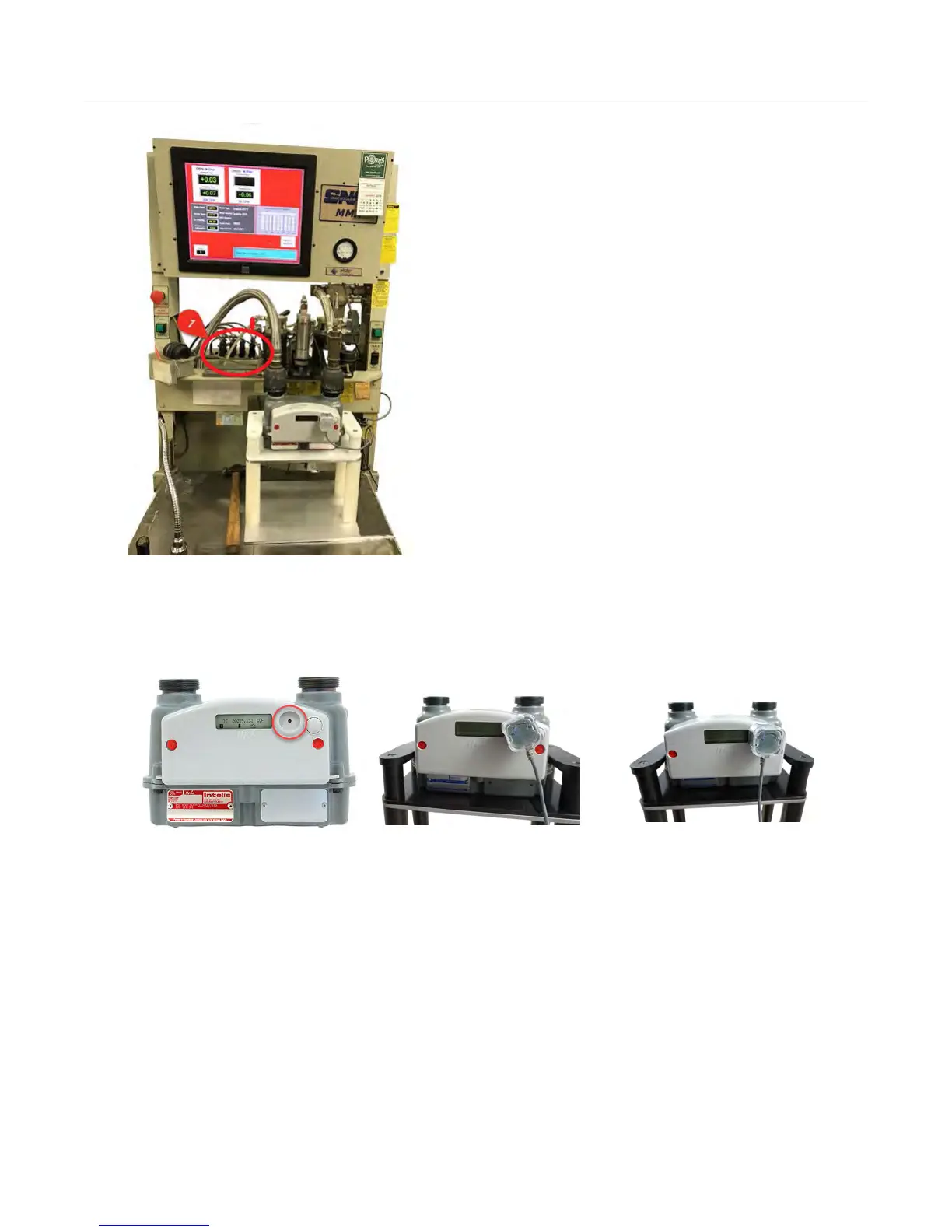
11. Connect the Intelis Gas Meter end of the SNAP pulse prover cable to the Intelis Gas
Meter optical port by firmly pressing the aluminum round threads of the cable into the
port. Begin by positioning the cable at the 4:30 o'clock position. T
ighten the cable to the
6:30 o'clock position.
Note: The Intelis Gas Meter will automatically go into T
est Mode (Menu 6) when the pulse
prover output cable is connected.
12. Start the proving test by clicking RUN on the SNAP prover.
13. Verify the LED blinks (pulses) when the air begins to flow through the meter.
Proving the Intelis Gas Meter using the Measurement
Systems proving system
This section provides the information to set up an Intelis Gas Meter using a Measurement
Systems proving system.
Proving the Intelis Gas Meter
Intelis Gas Meter Installation Guide TDC-1782-002 32
Proprietary and Confidential