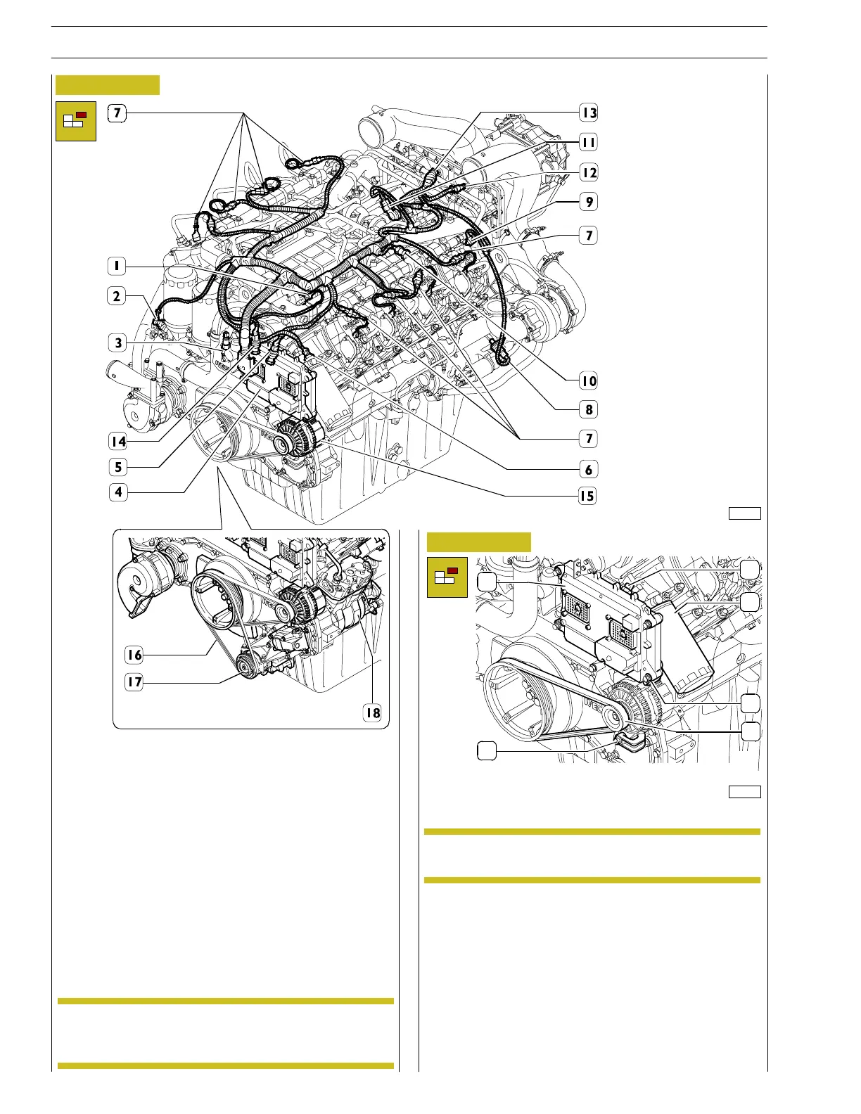
- Remove the engine wiring: disconnect the wiring from
cool ant temperature sensor (1), sensors (2 and 14), XJ2
connector from ADEM III (4), atmospheric pressure
sensor (5), fuel temperature sensor (6), electro injector
(7), engine speed sensor (8), timing system speed sensor
(9), co mmon rail fuel pressure sensor (10), co mmon rail
high pressure cont rol solenoid valve (11), turbo—blower
air temperature senso r (12) and air pressure sensor in
the intercooler (13).
Figure 3
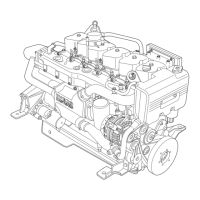
Figure 4
- Remove the ADEM III engine management control unit
(2) from its mounting undoing the bolts for the flexible
mountings (3).
- Remove the atmospheric pressure sensor (4) from the
support.
- If present on the application, remove the flexible belt (16)
and the air conditioning c ompressor (17).
- Completely undo t he screw (5) and release the belt (6).
- Remove the alternator complete with bracket.
- Remove the control unit support complete with diesel
filter mounting.
112865
The oil filter blockage sensor (3) and the alternator
(15)arenotconnectedtotheenginelead.
NOTE
On the DRAGON and GRIFFON applications, the
fuel filters are fitted in a remote position.
NOTE
103227
5
6
3
4
1
2
- Remove t he diesel filt er (1) using tool 99360091.
12
SECTION 3 - INDUSTRIAL APPLICATION
VECTOR 8 ENGINES
Base - April 2006 Print P2D32V001E