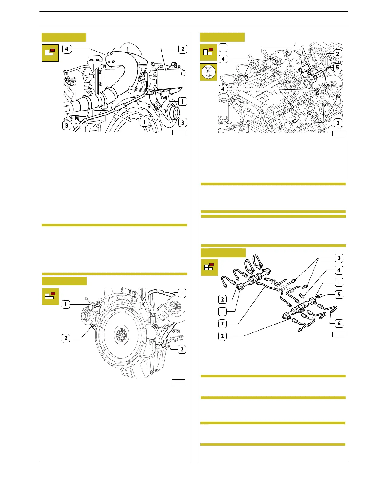
Figure 5
103479
- Remove the pipes (1) to the blow-by filter (2) from the
flywheel side.
- Undo the 4 bolts fixing the filter casing to the air intake
manifolds from the turbocharger body to the heat
exchanger (air/air intercooler) removed previously
together with the air filters.
- Loosen the bands (3) on both sides of the hoses near
the turbochargers.
- Undo the bolts from underneath the bracket above the
flywheel to release the manifold (4). Remove the
manifold securing it appropriately.
After having checked the cleanliness inside the
manifold, seal the three ends to preserve it.
Check the wear of the hoses in the case of obvious
signsofcracksorifthereisalossinthenormal
flexibility replace them.
NOTE
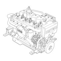
Figure 6
- Remove the lubrication pipes from both turbines:
disconnect the oil intake pipe (1) from the cran kcase at
the top flange on the body of the turbo—blower and the
exhaust pipe (2) from the bottom of the body of the
turbo—blower and from the seat on the sump.
- Also remove the oil pipes at the sump from the blow-by
filter removed previously.
- Remove the band fastening the pipe on the flywheel
casing and then undo it from the flange on the engine
sump.
103228
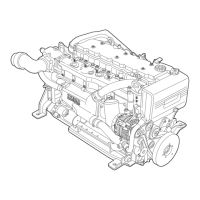
Figure 7
- Loosen the rail c h eck u-bolt (4) fixing screws.
- Disassemble th e assembly of the delivery pipes (1) from
the high pressure pump (2) and t he ones on the
electro-injectors;
unscrew the washers (3) with a 99368506 wrench.
- Remove the rail assembly
- Disassemble the diesel fu el exhaust pipes from the
overpressure valve rail (5).
Plug all the pipes in order to prevent possible
contamination. Unscrew the fittings seeing to
protect the seal surfaces.
89790
Figure 8
RAIL ASSEMBLY FOR G-DRIVE / DRAGON /
SPRINKLER APPLICATIONS
Common rail (1), flow limiting device (2), delivery pipes to
the rail from th e high pressure pump (3), pressure sensor
(4), overpressure valve (5).
If it is h ard to disassemble, loosen the washers of the
electro-injector supply pipes on the rail side, of the
compensation pipes between the rail and the rail
side supply.
- Remove all the diesel return pipes: those of the injectors
and the one from the high—pressure pump.
89791
If there is a malfunction with components (2), (4)
or (5), replace the rail assembly (1).
NOTE
The RAIL assembly for GRIFFON applications is
shown on page 21 of the section 2.
NOTE
NOTE
NOTE
On the be nch sepa ra te the pip e s that are betwee n the rail and
the support. Che ck the cond itions of the thre ad sea l conic
surfaces. Plug all pipes in order to prevent contamination
SECTION 3 - INDUSTRIAL APPLICATION
13
VECTOR 8 ENGINES
Print P2D32V001E Base - April 2006