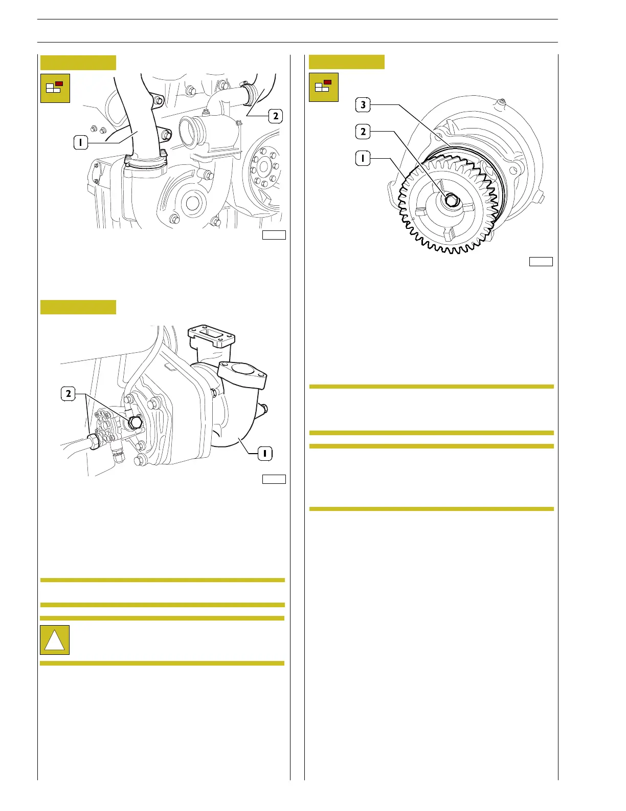
- Remove the pipe (1) which connects the pump to the
water/oil heat exchanger fitted between the two banks
and remove the hose (2) between the thermostat body
and the elbow connector on the pump.
!
Fully drain off the c oolan t contained in the cooling
pump.
Figure 9
103229
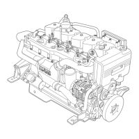
- Support the cooling pump (1) and undo the four fixing
nuts.
Thoroughly release t he pump assembly for t he inlet
pipes.
- Disconnect the pipes (2) fro m t he rear of the gear casing.
Figure 10
103230
Seal the pipes and the connectors on the pump.NOTE
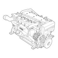
- Inspect the hydraulic pump and especially the state of
wear of the teeth of the driving gear (1) (both those
receiving motion from the gearbox and th e front teeth
transmitting motion to the pump of the primary cooling
circuit).
- Replace if there is exc essive gear wear: lock gear (1)
rotation properly and loosen sc rew (2). Disassemble the
gear and set the s crew aside.
Figure 11
The gear has a left-hand locking screw.
The hydraulic sealing of the pump is assured by a
gasket (3). If the same pump is used again replace the
above mentioned seal before reassembly.
89792
NOTE
NOTE
14
SECTION 3 - INDUSTRIAL APPLICATION
VECTOR 8 ENGINES
Base - April 2006 Print P2D32V001E