Figure 12
Figure 13
Figure 14
Figure 15
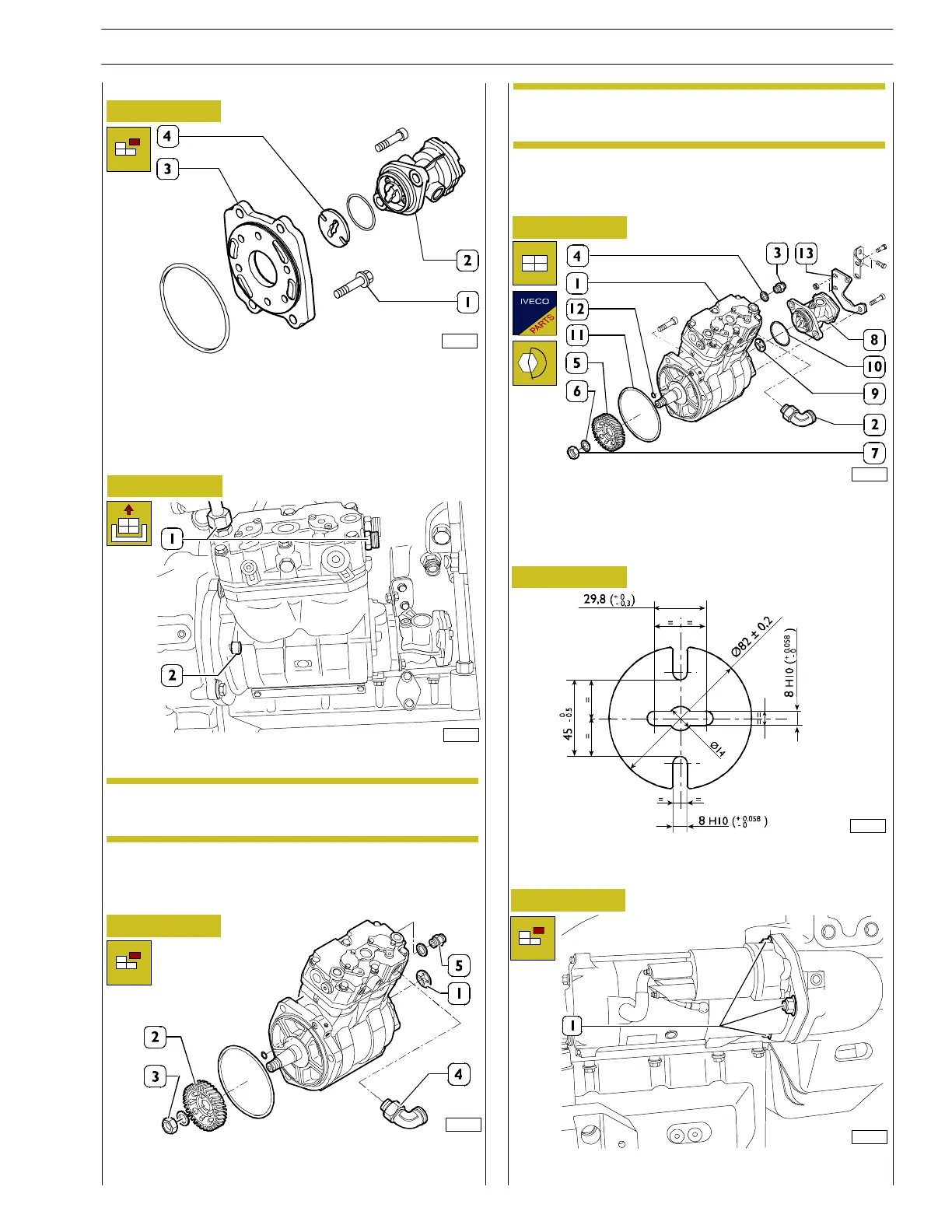
- Unscrew the three scre ws (1) fixi ng the supp or t to the
gearbox and remove the the low—pressure supply pump
(2).
- On the bench, go ahead and remove the support (3) and
separate the low—pressure supply pump (2); in addition,
remove the coupling drive (4).
103475
For G-DRIVE, GRIFFON and SPRINKLER applications
For DRAGON applications
- Disconnect the coolant connecting pipes (1).
89698
It is advisable to plug both the pipes and the ports on
the compressor that has to be shipped for overhaul.
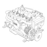
- Unscrew t he fixin g screw s of brakets (13, Figure 15)
- Unscrew th e screws (2, Figure 13) fixing the compressor
on the spacer.
NOTE
- Take the compressor to the workbench and separate
the l ow-pressure pump (if not previously removed ).
Recover the universal joint (1), checking its state of
wear.
- After firmly secu rin g the compressor in a vice, remove
the gear (2) by unscrewing the nut (3) and using a specific
extractor. In addition, remove the fittings (4) and (5).
- Unsc rew the screw (13) t hat fixing the LPP (8) to air
compressor.
- Divide the LPP (8) from air compressor and recover
coupling drive (9) and O-ring (10).
For all applications
81969
NOTE
89697
- Check the state of wear of the coupling drive and its
coupling w ith th e low—pressure pump spindle.
Figure 16
83490
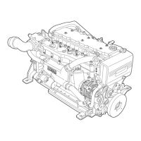
- Remove the starter motor by unscrewing the three nuts
(1).
82205
Figure 17
SECTION 3 - INDUSTRIAL APPLICATION
15
VECTOR 8 ENGINES
Print P2D32V001E Base - April 2006