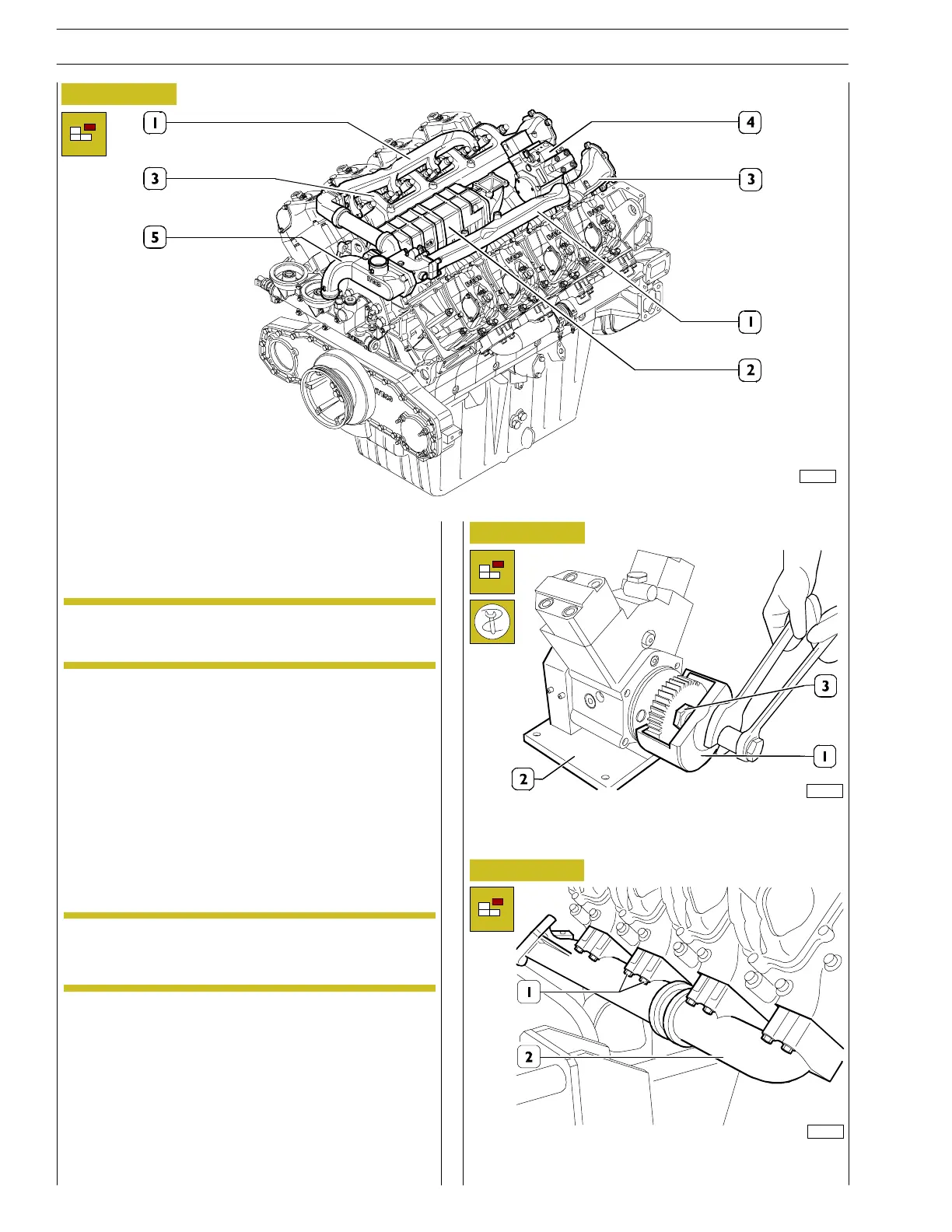
Figure 23
- Unscrew the fixing screws and remove the water outlet
pipes (1) from the heads.
- Remove the thermostat casing (5).
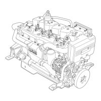
Figure 24
- Remove the driving gear wi th the aid o f tools 99368516
(1), 99368517 (2) that permit unscrewing the M24 x 1.5
nut (3).
- Then remove the engine water/oil cooler (2),
unscrewing the M10 x 40 mm screws (three on both
sides).
- Remove the diesel supply pipe from the high—pressure
pump (the coupling has been removed together with the
ADEM III control unit support).
- Remove the diesel recovery piping.
- Remove the in take manifolds (3), remove the gaskets
and remove the hi gh pressure pump (4) from the
flywheel casing complete with gear.
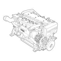
Figure 25
- Unscrew the screws (1) and remove the exh aust
manifolds (2) on both sides comprehensive of seals.
103190
82214
NOTE
Separate the screws appropriately, marking their
placement t o facilitate assembly.
NOTE
Separate the screws appropriately, marking their
placement t o facilitate assembly.
82215
18
SECTION 3 - INDUSTRIAL APPLICATION
VECTOR 8 ENGINES
Base - April 2006 Print P2D32V001E