Micro-JLT GNSS™ User Manual
12 © 2019 Jackson Labs Technologies, Inc.
EFC Damping: overall IIR filter time constant. higher values increase loop time-constant. Jackson
Labs Technologies, Inc. typically uses values between 10 to 50. Setting this value too high may cause
loop instability.
Phase compensation: this is the Integral part of the PID loop. This corrects phase offsets between
the Micro-JLT GNSS™ 1PPS signal and the UTC 1PPS signal as generated by the GNSS receiver.
Set higher values for tighter phase-following at the expense of frequency stability. Typical values
range from 4 - 30. Setting this value too high may cause loop instability.
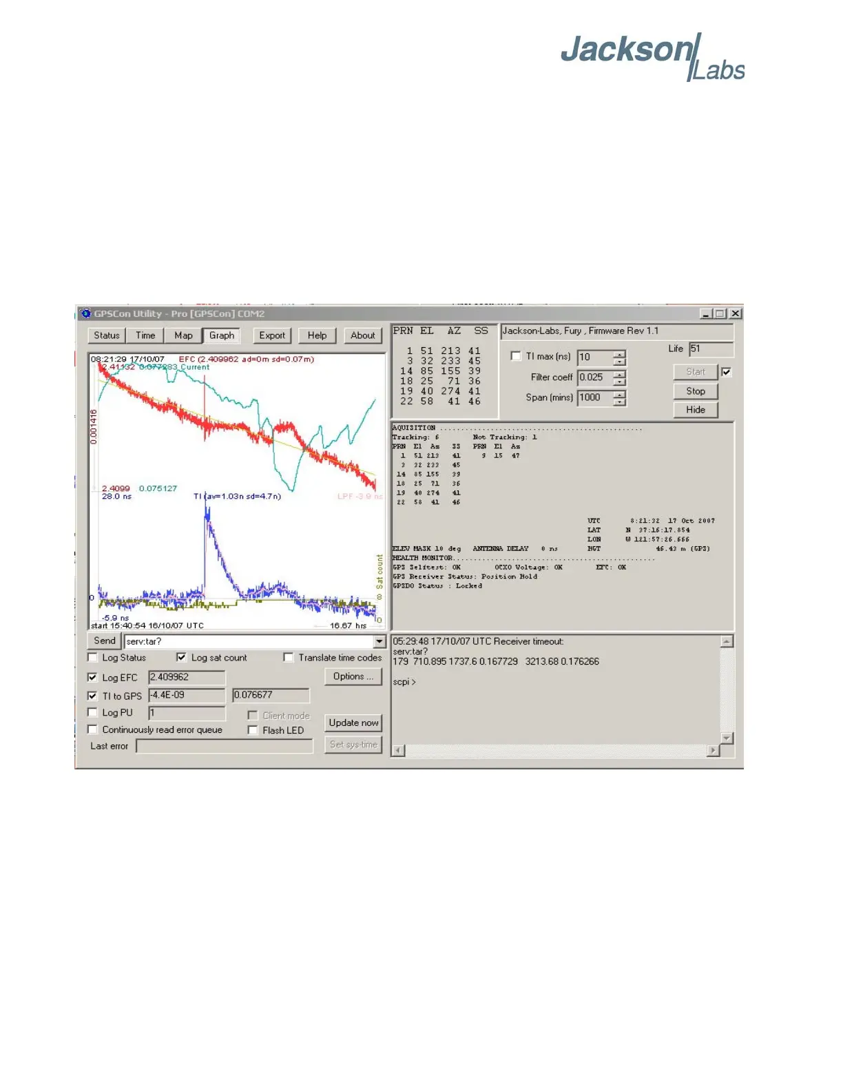
A well-compensated unit will show performance similar to the plot shown in Figure 2.4 when
experiencing small perturbations:
Figure 2.4 Micro-JLT GNSS™ phase compensation plot