HYDROSTATIC POWER TRAIN
4181384 First Edition 5-13
5
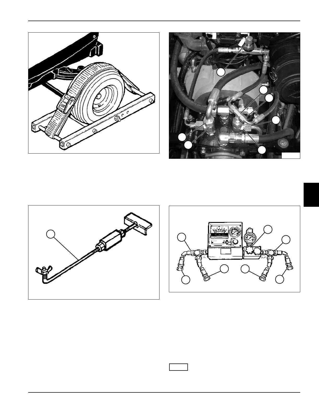
Figure 5-9
4. Install wheel restraint to rear wheel.
5. Lift and support the machine so that the front wheels
are off the ground.
6. Disconnect traction pump control rod from pump
control arm.
Figure 5-10
7. Install flow lock tool (1) and secure to pump control
arm.
Figure 5-11
8. Close tow valve (2) completely by turning clockwise.
9. Disconnect and plug hose (4).
10. Install a cap to fitting (3).
11. Disconnect hoses (5 and 8).
Figure 5-12
12. Connect test hose (14) of flow meter inlet to fitting
(6).
13. Connect test hose (13) of flow meter outlet to fitting
(7).
14. Connect hose (8) to flow meter outlet (12).
15. Connect hose (5) to flow meter inlet (15).
16. Open flow meter valve (10) completely before
starting engine.
NOTE
Verify engine rpm is within specification (3150 rpm ± 50)
to ensure accurate hydraulic test results.
TN1329
1
TN1364
TN1293
2
4
8
7
3
6
5
14
TN1357
13
10
15
12
9
11