HYDROSTATIC POWER TRAIN
4181384 First Edition 5-39
5
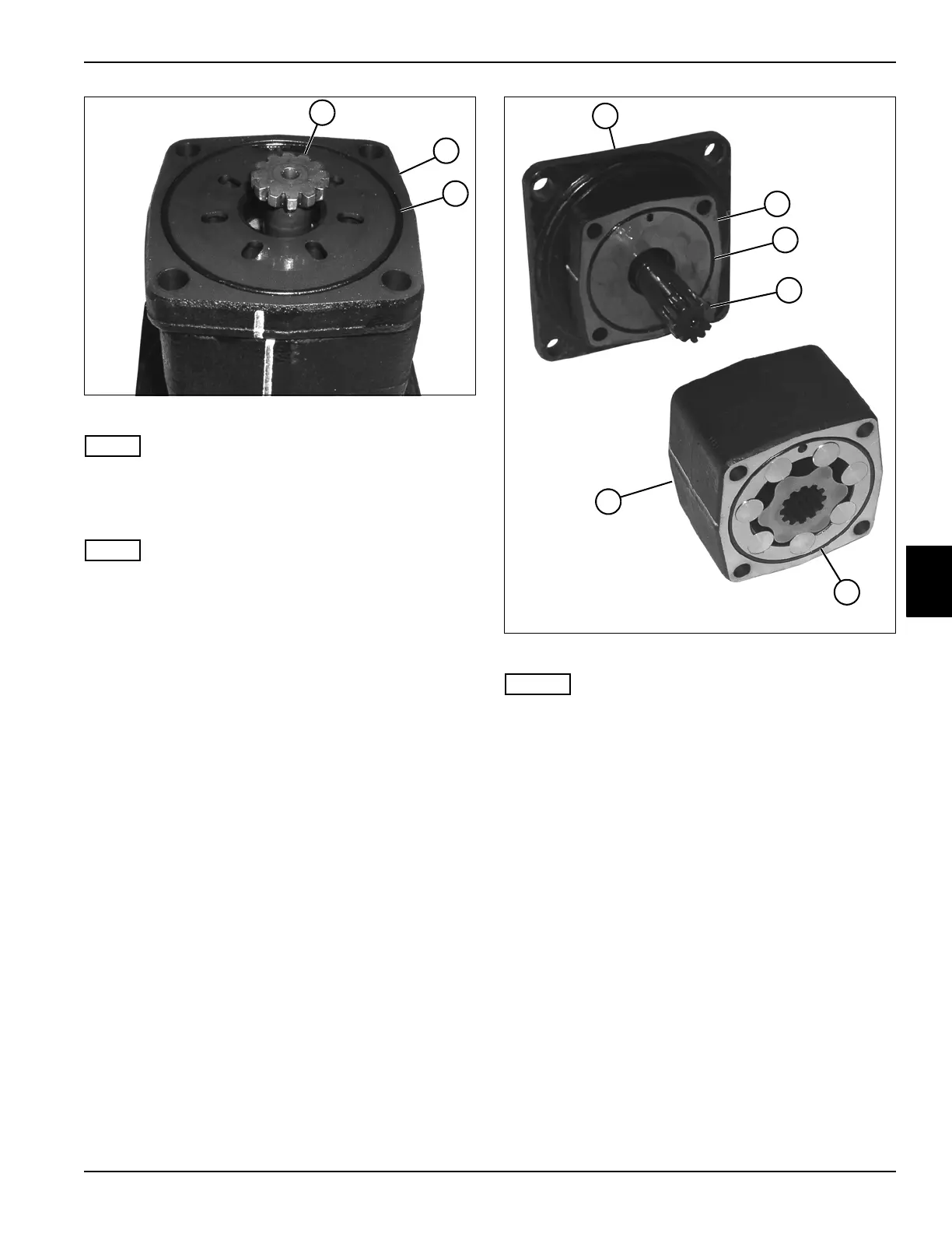
Figure 5-72
NOTE
Record the orientation of the valve drive before removing
to ensure correct installation.
7. Remove the valve drive (17).
NOTE
Record the orientation of the channel plate before
removing to ensure correct installation.
8. Remove the channel plate (18).
9. Remove the O-ring (19) from channel plate (18).
Figure 5-73
NOTES
• Do not disassemble the gear wheel set. If
replacement is necessary, replace the entire
assembly.
• Record the orientation of all components before
removing to ensure correct installation.
10. Remove the gear wheel set (25) from the
intermediate plate (21).
11. Remove the cardan shaft (23) from the intermediate
plate (21).
12. Remove the intermediate plate (21) from the bearing
housing (20).
13. Remove O-ring (22) from the intermediate plate (21).
14. Remove O-ring (24) from the gear wheel set (25).
TN1297
17
18
19
TN1296
21
25
23
20
22
24