6-32 4181384 First Edition
HYDRAULICS
6
2. Before performing this test, perform cutting unit
system test leaving flow meter connected as
outlined.
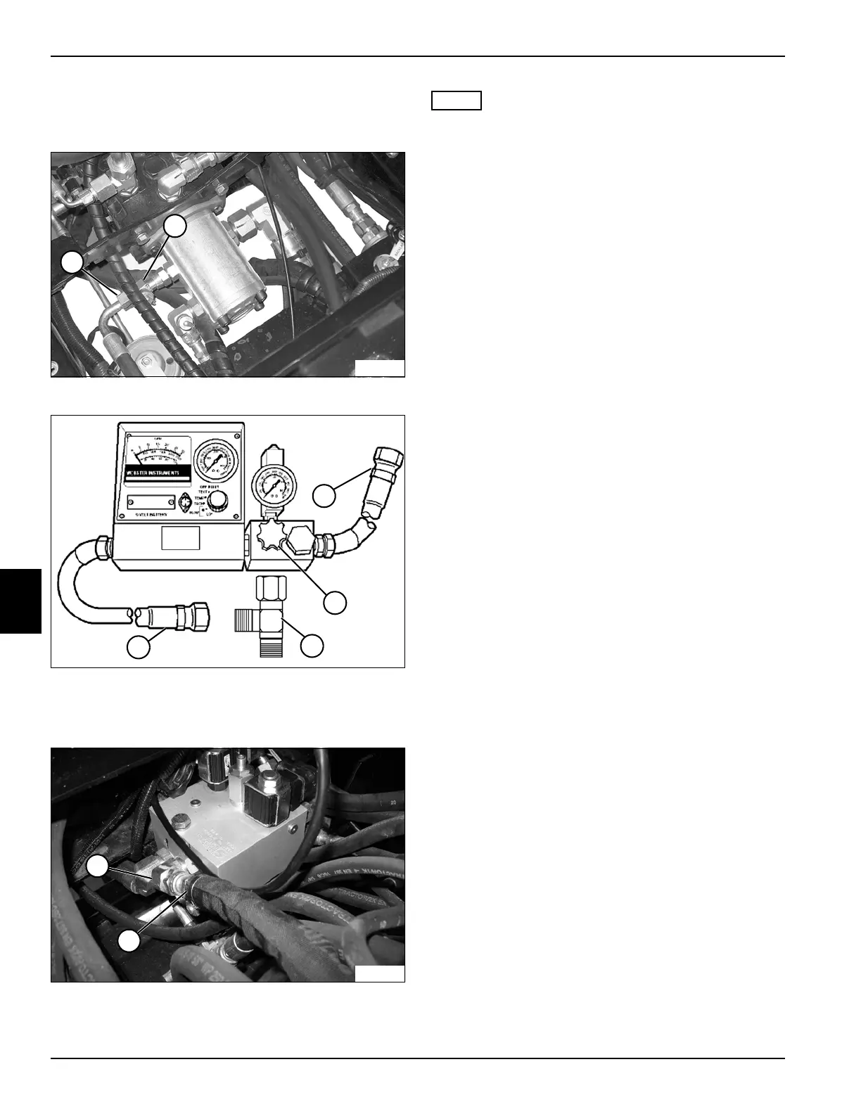
Figure 6-22
Figure 6-23
3. Disconnect hose (1) and install blocking disk to tee
fitting (5).
Figure 6-24
4. Open flow meter valve (4) completely.
NOTE
Verify engine rpm is within specification (3150 rpm ± 50)
to ensure accurate hydraulic test results.
5. Start engine and run at full throttle (3150 rpm ± 50).
6. Use the flow meter to warm the hydraulic oil. Turn the
flow meter valve until a reading of 1525 psi (105 bar)
or one half of the relief valve rating is reached. Warm
oil to 120—150°F (49—65°C), open valve fully after
operating temperature is reached.
7. Slowly close flow meter valve until pressure reaches
2300 psi (159 bar). Read and record the cutting
unit/charge pump loaded flow.
8. Stop engine.
9. Calculate cutting unit/charge pump leakage.
(Step 15 of previous test – Step 7 / Step 15 of
previous test x 100 = Leak Percentage)
Is cutting unit/charge pump leakage 10% or less?
YES The cutting unit/charge pump is good.
Proceed to step 18.
NO Proceed to next question.
Is cutting unit/charge pump leakage 11% to 20%?
YES The cutting unit/charge pump is marginal.
Additional testing is required.
NO Proceed to next question.
Is cutting unit/charge pump leakage 21% or
more?
YES Replace cutting unit/charge pump. (See
“Tandem Pump” on page 6-44.)
10. Disconnect and remove test equipment. Install all
hoses and fittings as noted prior to removal.
11. Check hydraulic oil level. Add oil as needed. (Refer to
“Safety, Operation, and Maintenance Manual” for
correct oil specifications.)
TN1124
1
2
5
6
TN1363
4
3
TN1362
7
8